85
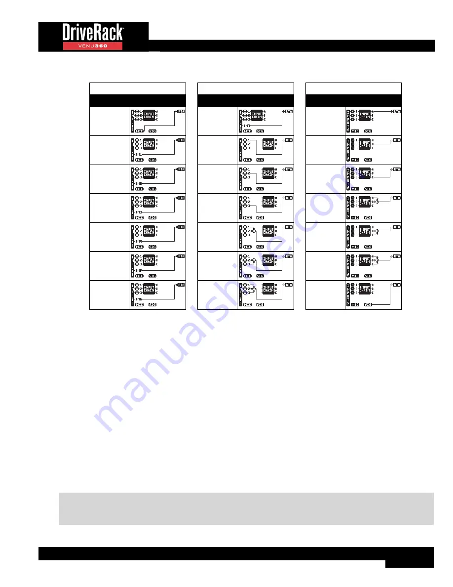
RTA Source Routing Options
RTA Source Options
Description Routing Diagram
Route RTA
MIC
Route IN1
(Analog 1)
Route IN2
(Analog 2)
Route IN3
(Analog 3)
Route IN4
(AES 1)
Route IN5
(AES 2)
Route IN6
(AES 3)
RTA Source Options
Description Routing Diagram
Route IN7
(AES 4)
Route Bus 1
Route Bus 2
Route Bus 3
Route Bus
1+2
Route Bus
2+3
Route Bus
1+2+3
RTA Source Options
Description Routing Diagram
Route Bus A
Route Bus B
Route Bus C
Route Bus
A+B
Route Bus
B+C
Route Bus
A+B+C
Route Signal
Generator
•
RATE
[SLOW, FAST]
Adjusts how quickly the RTA will sample the audio and update its display. When set to FAST, instantaneous peaks can
be seen, but the RTA will react very quickly, making it difficult to use for some tasks. When set to SLOW, the RTA will
update at a slower rate, making it easier to read the amplitude levels of all frequencies.
•
GRAPH OFFSET
[0 dB - 40 dB]
Adjusts the signal level entering the RTA. Adjust this parameter so that the full frequency spectrum of the monitored
signal can be displayed within the RTA graph.
•
GRAPH TYPE
[OPT1 - OPT6]
Selects between six different RTA graph view types. Select the type which looks best to you.
•
GRAPH HOLD
[0.5s - 5.0s]
Sets the length of time the RTA will “hold” peaks in the display, providing an easy-to-read visual indication of peak levels,
even after they’ve already passed. Time units are in seconds.
•
SIGNAL GENERATOR
[OFF, ON]
Turns the built-in signal generator on or off. The Signal Generator can be used for signal routing verification, system
troubleshooting, or manual system calibration.
NOTE:
The Signal Generator will automatically default to off whenever a new configuration is applied, a different
preset is loaded, or the Setup Wizard is completed. This is a safety feature to prevent accidental damage to system
components.
Summary of Contents for DriveRack VENU 360
Page 1: ...Owner s Manual ...


