Figure 1M
Figure 1K
Figure 1L
MobileTrak5 Mechanical End Panel Installation
Instructions
Page 20
SEE PAGE 18
FOR PROPER
HANDLE
ALIGNMENT
UPPER 3 PIECE
END PANEL
LOWER 3 PIECE
END PANEL
1/4-20 x 1
HEX HEAD BOLT
3 PIECE WOOD END PANEL SHOWN
1 PIECE & STEEL ARE SIMILAR
T-HANDLE
3/8-24
JAM NUT
CHAIN LOCK CAM
#8-32 MACHINE SCREW
END PANEL
T-HANDLE
LOCK CAM
INSTALLING T-HANDLE
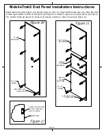
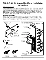
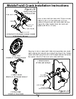
Install T-handle to end panel by inserting threaded portion through hole in end panel (see Figure 1K).
On 3 piece end panels, handle hole is located on bottom panel. On 1 piece end panels handle hole is
lower hole on panel. Attach to wood panel with #8-32 x 7/8" machine screw. Attach to steel end
panel with #8-32 x 3/8" machine screws. Screw first 3/8 jam nut on to T-handle. Place lock cam on
handle shaft as shown in Figure 1J. Finger tighten second jam nut onto handle shaft. Distance cam
1/8" from end of handle shaft (see Figure 1L). Fully tighten jam nuts.
INSTALLING END PANELS
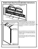
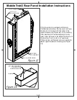
If using steel end panels, attach steel panel spacers to drive tower using (4) #8 x 3/8 Tek screws
(see Figure 1M). On all panels, align T-handle and chain lock bar according to instructions on Page
18. Align male clips on end panel with female clips on uprights. Using smooth, firm pressure, press
end panels onto uprights. Tighten (2) 1/4-20 x 1" hex bolts through holes next to crank shaft.
UNLOCKED
POSITION
LOCKED
POSITION
0.125
#8 x 3/8 TEK SCREW
STEEL PANEL SPACER
Summary of Contents for MobileTrak5
Page 7: ...THIS PAGE INTENTIONALLY LEFT BLANK Page 7 MobileTrak5 Installation Instructions ...
Page 18: ...MobileTrak5 Installation Instructions THIS PAGE INTENTIONALLY LEFT BLANK Page 18 ...
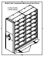
Page 22: ...MobilTrak5 Completed Mechanical End Panel Page 22 3 PIECE SHOWN 1 PIECE SIMILAR ...
Page 23: ...Page 23 MobileTrak5 Installation Instructions THIS PAGE INTENTIONALLY LEFT BLANK ...

