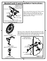
Figure 1N
HANDLE AND HUB
INSTALLATION
3 SPOKE WITH STANDARD HANDLE SHOWN
OTHERS ARE SIMILAR
CRANK DISC
SHOWN W/ FOLDING HANDLE
3 SPOKE CRANK
SHOWN W/ STANDARD HANDLE
1 SPOKE CRANK
SHOWN W/ BALL KNOB
Figure 1O
MobileTrak5 Crank Installation Instructions
Page 21
CRANK SHAFT HUB
HANDLE
M10 x 1.5 NUT
1/4" LOCK WASHER
1/4-20 x 1/2
HEX BOLT
KEY
5/16 WIDE
FLAT WASHER
5/16-18 x 5/8
HEX FLANGE BOLT
HUB COVER
3 SPOKE SHOWN
OTHERS ARE SIMILAR
Align 3 crank shaft hub holes with 3 holes in crank.
Install 1/4-20 x 1/2" hex bolts with 1/4" lock
washers through crank, into crank shaft hub (see
Figure 1M). Place handle/ knob into crank and
tighten with M10 x 1.5 nuts.
Place key in slot on crank shaft. Slide crank assembly onto crank
shaft, aligning hub slot with key on shaft (see Figure 1N). Tighten
crank onto shaft using 5/16-18 x 5/8" flanged bolt and 5/16 wide
flat washer. Place hex hub cover over crank shaft hub.
Summary of Contents for MobileTrak5
Page 7: ...THIS PAGE INTENTIONALLY LEFT BLANK Page 7 MobileTrak5 Installation Instructions ...
Page 18: ...MobileTrak5 Installation Instructions THIS PAGE INTENTIONALLY LEFT BLANK Page 18 ...
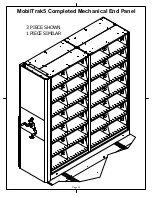
Page 22: ...MobilTrak5 Completed Mechanical End Panel Page 22 3 PIECE SHOWN 1 PIECE SIMILAR ...
Page 23: ...Page 23 MobileTrak5 Installation Instructions THIS PAGE INTENTIONALLY LEFT BLANK ...


