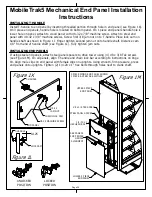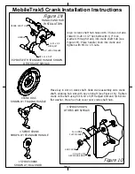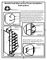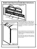
Figure 1C
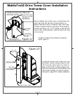
SHOWN WITHOUT END PANELS OR
DRIVE BOX COVER.
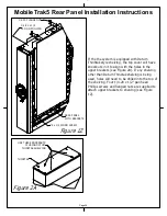
Figure 1D
MobileTrak5 Drive Tower Cover Installation
Instructions
Page 16
PLACE HOLE
TANGENT WITH
BRACKET
PLACE LOCK CAM IN
VERTICAL POSITION
FOR SMOOTH
INSTALLATION
T-HANDLE (SHOWN
WITH OPTIONAL LOCK)
Before installing drive tower cover or mechanincal end
panel, the chain lock bar and T-handle need to be
aligned. Slide the lock bar so that the hole in the chain
lock bar is tangent with the right side of the mounting
bracket (see Figure 1C). Turn T-handle so that the lock
cam is in the vertical position, which will allow it to slide
in the lock bar.
CHAIN LOCK BAR
MOUNTING
BRACKET
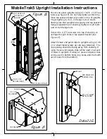
If using drive tower cover, place cover over
drive tower. Secure in place using (4) #8 x
3/8" Tek screws (see Figure 1D). Check to
make sure that the T-handle engages lock
bar by turning handle to locked position and
ensuring the carriage is locked in position.
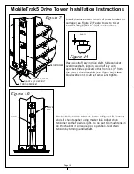
Continue to page 23 for handle installation.
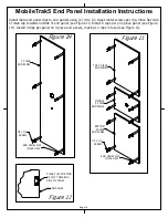
If system includes fully enclosed end panels,
skip to page 19.
#8 x 3/8"
TEK SCREW
1/4-20 x 1 1/4"
HEX HEAD BOLT
DRIVE TOWER COVER
SEE ABOVE
FOR REQUIRED
LOCK ALIGNMENT
Summary of Contents for MobileTrak5
Page 7: ...THIS PAGE INTENTIONALLY LEFT BLANK Page 7 MobileTrak5 Installation Instructions ...
Page 18: ...MobileTrak5 Installation Instructions THIS PAGE INTENTIONALLY LEFT BLANK Page 18 ...
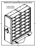
Page 22: ...MobilTrak5 Completed Mechanical End Panel Page 22 3 PIECE SHOWN 1 PIECE SIMILAR ...
Page 23: ...Page 23 MobileTrak5 Installation Instructions THIS PAGE INTENTIONALLY LEFT BLANK ...

