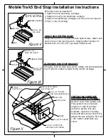
Figure V
Figure W
Figure X
MobileTrak5 End Stop Installation Instructions
Page 12
RAIL
END STOP
5/16-18 x 3/4 ALLEN
BUTTON HEAD SCREW
RUBBER BUMPER
1/4-20 x 3/8
PAN HEAD
5/16-18 x 3/4
ALLEN CAP SCREW
END STOP
RUBBER BUMPER
1/4-20 x 3/8
PAN HEAD
5/16-18
NYLOCK NUT
MARK & DRILL USING
21/64" DRILL BIT
#10 x 1/2" PHILIPS
PARTICLE BOARD SCREW
LOCK PLATE
SYSTEM LOCK
5/16-18 x 3/4"BUTTON
HEAD ALLEN CAP SCREW
COVER
#8 x 3/8 TEK SCREW
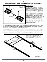
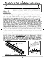
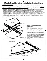
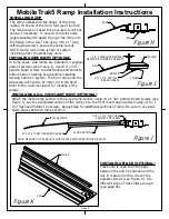
End stops must be installed if:
1. System has no stationary carriages.
2. System has only one stationary carriage.
3. System has stationary carriages, but they are not secured
to floor or top of decking.
ANGLE END STOP BRACKET
Using two 5/16-18 x 3/4 allen button head screws, fasten end
stop on top of rail (see Figure V). Attach rubber bumper to
bracket with 1/4-20 x 3/8" pan head Phillips screw.
ALUMINUM END STOP BRACKET
Using two 5/16-18 allen cap screws, attach end stop bracketon
top of rail with rubber bumper facing mobile carriages.
INSTALLING CARRIAGE
SYSTEM LOCK (OPTIONAL)
Remove cover from system lock.
Place system lock in desired
location on side of carriage.
Using the system lock as a
template, mark the mounting
holes and drill using a 21/64" bit.
Attach the lock using the 5/16-18
x 3/4" button head allen cap
screw.
Summary of Contents for MobileTrak5
Page 7: ...THIS PAGE INTENTIONALLY LEFT BLANK Page 7 MobileTrak5 Installation Instructions ...
Page 18: ...MobileTrak5 Installation Instructions THIS PAGE INTENTIONALLY LEFT BLANK Page 18 ...
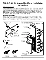
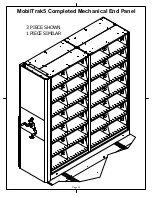
Page 22: ...MobilTrak5 Completed Mechanical End Panel Page 22 3 PIECE SHOWN 1 PIECE SIMILAR ...
Page 23: ...Page 23 MobileTrak5 Installation Instructions THIS PAGE INTENTIONALLY LEFT BLANK ...


