Datex-Ohmeda AS/3 Compact Monitor Technical Reference Manual Download Page 24

Datex-Ohmeda AS/3 Compact Monitor, CS/3 Compact Monitor

16

Document No. 896 623
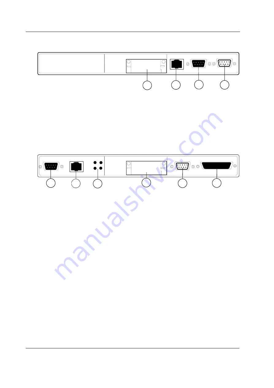
3.3.2

Rear panel connectors

2

3

4

1

Figure 8

Rear Panel with Memory, CPU and UPINET Boards

(1)


Software Cartridge, on CPU board, B-CPU2 or B-CPU3,
or Software Card drive and lid for back plate on B-CMCPU4,
connector on B-CMCPU4 is reserved for future use (not in figure).

(2)


Network connector

(3)


Network identification plug connector

(4)


Serial communication connector

1

2

3

4

5

6

Figure 9

Rear Panel with NET, CPU and UPI Boards. NET and UPI Boards can be
replaced by UPINET board.

(1)


Network identification plug connector

(2)


Network connector

(3)


Ethernet status LEDs

(4)


Software Cartridge, on CPU board, B-CPU2 or B-CPU3,
or Software Card drive and lid for back plate on B-CMCPU4,
connector on B-CMCPU4 is reserved for future use (not in figure).

(5)


Serial communication connector

(6)


Parallel printer port, analogue & digital input/output connector

CAUTION


Turn the power off before making any rear panel connections.

NOTE

: Your monitor configuration may not include all circuit boards listed above.

Summary of Contents for AS/3 Compact Monitor

Page 1: ...otice Document No 896623 February 2000 Datex Ohmeda Inc 3 Highwood Drive Tewksbury MA 01876 Tel 978 640 0460 Fax 978 640 0469 www us datex ohmeda com Datex Ohmeda Division Instrumentarium Corp P O Box 900 FIN 00031 DATEX OHMEDA FINLAND Tel 358 10 394 11 Fax 358 9 146 3310 www datex ohmeda com Instrumentarium Corp All rights reserved ...

Page 2: ... Type BF or CF equipment The degree of protection against electric shock is indicated by a symbol on the parameter panel beside each connector Equipment is not suitable for use in the presence of a flammable anesthetic mixture with air or with oxygen or nitrous oxide Continuous operation according to the mode of operation In accordance with IEC 60529 Degree of protection against the harmful ingres...

Page 3: ...Product Service Guide continues 896 620 1 Hemodynamic Modules M NE12STPR M NE12STR M NE12TPR M NESTPR M NESTR M NETPR M ESTPR M ESTR M ETPR 1 896 619 Compact Airway Modules M CAiOVX M CAiOV M CAiO M COVX M COV M CO M C 2 896 621 Tonometry Module M TONO 3 896 622 1 EEG Module M EEG and EEG Headbox N EEG 4 889 881 5 Cardiac Output Modules M COP and M COPSv 5 885 935 7 Pressure Module M P Pressure Te...

Page 4: ......

Page 5: ...n to mains 17 3 3 4 Connection to Network 17 3 3 5 Inserting the parameter modules 17 3 3 6 Replacing the CPU Board B CMCPU4 18 3 3 7 Performing Factory Reset 19 3 3 8 Replacing the Software Cartridge of B CPU2 3 20 3 3 9 Replacing the CPU Board B CPU2 3 21 3 4 AS 3 Memory Board B CMMEM Installation w B CPU2 3 23 3 5 AS 3 Memory Board B CMMEM Installation w B CMCPU4 26 3 6 Network Board B NET Inst...

Page 6: ... 49 4 3 5 Connection to Nellcor N 200 49 4 4 Interfacing Datex OhmedaAS 3 Anesthesia Delivery Unit 49 4 5 Interfacing Dräger Cicero and Cato 50 4 6 Interfacing a printer 50 4 7 Interfacing a computer 50 4 8 UPI Board Output Signals 51 4 8 1 Digital Outputs 51 4 8 2 Analog Outputs 52 4 8 3 Setting the Analog Output Signals 53 4 9 Pressure Temp Module M PT Output Signals 54 4 9 1 Analog Outputs 54 5...

Page 7: ... can be replaced by UPINET board 16 Figure 10 Datex Ohmeda Compact Airway Module 39 Figure 11 Scavenging through Ventilator Reservoir 40 Figure 12 Connection Directly to a Scavenging System 40 Figure 13 Sample Gas Return to Patient Circuit in ADU 41 Figure 14 Bar Code Reader connected to the Compact Monitor 42 Figure 15 Monitor General Troubleshooting Flowchart 74 ...

Page 8: ...Datex Ohmeda AS 3 CM and CS 3 CMC Document No 896623 iv ...

Page 9: ...ring in intensive care units The monitor consists of the CM frame and modules There are single and double width modules containing one or more parameters The modules can be removed and inserted during operation The CM frame is equipped with a battery and also a built in recorder is available AS 3 Anesthesia Keyboard K ARK is available for AS 3 Compact Monitor 2 3 1 Figure 1 AS 3 CS 3 Compact Monit...

Page 10: ...out prior notice The information in this manual is believed to be accurate and reliable however the manufacturer assumes no responsibility for its use Datex Ohmeda assumes no responsibility for the use or reliability of its software on equipment that is not furnished by Datex Ohmeda 1 1 1 Related Documentation AS 3 Compact Monitor More information about the clinical aspects and technical backgroun...

Page 11: ...rent sections in this manual section names are written in italic typeface and enclosed in double quotes for example Cleaning and Care WARNING Warnings are written in bold D O Sans typeface The font size is 13 points The word warning itself is written in capitals CAUTION The font size is 13 points The word caution itself is written in capitals NOTE Notes are written like this using Bodytext Symbols...

Page 12: ...itor indicates the following warnings and cautions Electric shock hazard Do not open the cover or the back Refer servicing to qualified personnel For continued protection against fire hazard replace only with same type and rating of fuse Disconnect power supply before servicing Type BF IEC 601 1 protection against electric shock Type BF IEC 601 1 defibrillator proof protection against electric sho...

Page 13: ...ber Sub menu Selecting an alternative with this symbol in a menu opens a new menu The monitor is connected to the Datex Ohmeda Network Data card green and or the Menu card white is inserted Indicates the beats detected Respiration rate is measured using impedance respiration measurement ...

Page 14: ...the power cord The cord may get broken Do not use extension cords or adapters of any type External Connection Do not connect any other external devices to the monitor than those specified by Datex Ohmeda Fuse Replacement Replace the fuse with a fuse of the same type and with the same rating Explosion Hazard Do not use the monitor in the presence of flammable anesthetics Patient Safety Do not perfo...

Page 15: ...pment damage or malfunction Installation Leave space behind the monitor to allow proper ventilation Before Use Allow two minutes for warm up and note any error messages or deviations from normal operation Clean side panel fan dust filter once a month or whenever necessary Autoclaving and Sterilizing Do not autoclave any part of the monitor Do not gas sterilize the modules Cleaning and Service Do n...

Page 16: ...n this manual Do not short circuit the battery terminals short circuiting the battery may produce a very high current which damages the battery Do not dispose of the battery into open flame nor put the battery near fire as it may explode Do not disassemble the battery It contains electrolyte which may damage clothing or cause injury to skin or eyes If exposed to electrolyte wash the injured area w...

Page 17: ...AS 3 and CS 3 System The CPU bus is a parallel communication channel used only for internal data transfer between the boards connected to one frame It is based on the ISA bus used in the IBM PC computers Data is transferred on this 16 bits wide bus using the CPU clock frequency The module bus is used to connect the parameter modules to the frame It based on the widely used industry standard RS 485...

Page 18: ...modules and CPU are doing their job the UPI processor takes care of all functions needed to transfer the data between modules and CPU And at the same time the processor on display control board is doing pixel calculations for graphics This kind of parallel processing gives one major advantage to centralized processing Each time new modules or boards are added to the system the processing power is ...

Page 19: ...ected Each module type has a unique name which UPI uses to address its messages If there are two modules of the same type they both answer at the same time This results an error and thus two similar modules are not allowed in one frame Module Bus Microcontroller AS 3 Bus Dual port RAM UPI Board CPU Bus Figure 4 Principle of UPI operation The microprocessor on the UPI board collects all information...

Page 20: ...ard from the software card UPI OR UPINET Board CPU Board Display Controller Board Program Memory Program Memory Program Memory CPU BUS Software Cartridge w B CPU2 3 or w B CMCPU4 Software Card Figure 5 Software loading 2 6 Parameter modules The detailed structure of the parameter modules depends on the specific needs for each individual parameter Some common parts can be found inside the modules h...

Page 21: ...3 Patient Peripheral drivers Isolation transformer RS485 drivers Opto isolation Power Reset Data Analog electronics Module keys 15V 5V 12V Module Bus A D converter CPU RAM EEPROM Patient isolation Figure 6 General structure of parameter modules ...

Page 22: ...ged If any of the components is damaged contact the shipper 4 Confirm that all components are included If any of the components is excluded contact your Datex Ohmeda distributor 3 2 Choosing location Consider the following aspects Lighting Space Connections Electromagnetic and radio frequency interference Atmosphere 3 3 Assembling the AS 3 CS 3 Compact Monitor Frame Mounting of the Compact Monitor...

Page 23: ...s 1 Dust filter 2 Recorder optional 3 Connector for Remote Controller Anesthesia Keyboard K ARK and Bar Code Reader 4 Potential equalization 5 Mains power inlet 6 Network connectors on B NET B CMNET optional 7 Device plate with voltage information 8 Network connectors on B UPINET B UPI optional 9 Insertion slots for memory cards optional ...

Page 24: ...n connector 1 2 3 4 5 6 Figure 9 Rear Panel with NET CPU and UPI Boards NET and UPI Boards can be replaced by UPINET board 1 Network identification plug connector 2 Network connector 3 Ethernet status LEDs 4 Software Cartridge on CPU board B CPU2 or B CPU3 or Software Card drive and lid for back plate on B CMCPU4 connector on B CMCPU4 is reserved for future use not in figure 5 Serial communication...

Page 25: ...twork symbol and Connected to Network message are displayed on the upper part of the screen NOTE The network symbol will not be displayed if the battery symbol is displayed on the upper part of the screen 3 3 5 Inserting the parameter modules Insert each plug in parameter module into a module slot Firmly press the module in position NOTE Do not use two or more modules with identical functions in t...

Page 26: ...tor LED is switched off 2 Unscrew the six screws holding the back plate in position and remove the plate WARNING The Compact Monitor is always energized by the internal battery Do not touch any exposured wiring or conductive surface with metallic object while the back plate is off or electric failure may result CAUTION The Compact Monitor is always energized by the internal battery A short circuit...

Page 27: ...rmly press the board in position 7 Replace PC boards removed earlier and secure the boards 8 Attach the back plate removed earlier 9 Reconnect the Power Cord and turn the power on 10 Perform factory reset 3 3 7 Performing Factory Reset NOTE The factory reset is necessary after replacing software and after replacing CPU board NOTE The factory reset will restore all your customized defaults includin...

Page 28: ...ce reset button on the rear panel for at least five seconds until the service reset indicator LED is switched off 2 Unscrew the two screws holding the software cartridge in position and remove the cartridge 3 Insert the new software cartridge into the empty slot and firmly press the cartridge in position Secure the cartridge two screws 4 Reconnect the power cord 5 Perform factory reset NOTE After ...

Page 29: ...s until the service reset indicator LED is switched off 2 Unscrew the six screws holding the back plate in position and remove the plate WARNING The Compact Monitor is always energized by the internal battery Do not touch any exposured wiring or conductive surface with metallic object while the back plate is off or electric failure may result CAUTION The Compact Monitor is always energized by the ...

Page 30: ...ses sensitive integrated circuits that can be damaged by an electrostatic discharge Careful handling of the board is therefore essential 6 Remove the EMC plate from the CPU Board 7 Insert the new CPU Board into the empty slot and firmly press the board in position Secure the new board 8 Replace the Software Cartridge and secure the cartridge with the two screws removed from the cartridge earlier 9...

Page 31: ... seconds until the service reset indicator LED is switched off 2 Unscrew the six screws holding the back plate in position and remove the plate WARNING The Compact Monitor is always energized by the internal battery Do not touch any exposured wiring or conductive surface with metallic object while the back plate is off or electric failure may result CAUTION The Compact Monitor is always energized ...

Page 32: ...osition and remove the plate 5 Unscrew the screw holding the cover plate in position and remove the plate 6 Remove the Memory Board B CMMEM including the connection board and the memory board from the protective anti static packaging Always hold the boards by the edges and wear a wrist grounding strap CAUTION The Memory Board B CMMEM comprises sensitive integrated circuits that can be damaged by a...

Page 33: ... memory board the bottom plate and the cover plate in position First secure the memory board with the three screws in the sequence indicated Then secure the memory board the bottom plate and the cover plate with the two screws M3x25 Finally secure the bottom plate four screws 1 2 3 9 Replace the back plate six screws 10 Reconnect the power cord ...

Page 34: ...for at least five seconds until the service reset indicator LED is switched off 2 Unscrew the six screws holding the back plate in position and remove the plate WARNING The Compact Monitor is always energized by the internal battery Do not touch any exposured wiring or conductive surface with metallic object while the back plate is off or electric failure may result CAUTION The Compact Monitor is ...

Page 35: ...e bottom plate in position and remove the plate 5 Remove the Memory Board B CMMEM including the connection board and the memory board from the protective anti static packaging Always hold the boards by the edges and wear a wrist grounding strap CAUTION The Memory Board B CMMEM comprises sensitive integrated circuits that can be damaged by an electrostatic discharge Careful handling of the board is...

Page 36: ...ition 7 Place the memory board the bottom plate and the cover plate in position First secure the memory board with the three screws in the sequence indicated Then secure the memory board the bottom plate and the cover plate with the two screws M3x25 Finally secure the bottom plate four screws 1 2 3 8 Replace the back plate six screws 9 Reconnect the power cord ...

Page 37: ...he rear panel for at least five seconds until the service reset indicator LED is switched off 2 Unscrew the six screws holding the back plate in position and remove the plate WARNING The Compact Monitor is always energized by the internal battery Do not touch any exposured wiring or conductive surface with metallic object while the back plate is off or electric failure may result CAUTION The Compa...

Page 38: ...crew holding the cover plate in position and remove the plate 5 Remove the Network Board B NET from the protective anti static packaging Always hold the board by the edges and wear a wrist grounding strap CAUTION The Network Board B NET comprises sensitive integrated circuits that can be damaged by an electrostatic discharge Careful handling of the board is therefore essential ...

Page 39: ... Board B NET into the empty slot and firmly press the board in position Secure the board with the screw removed from the cover plate earlier 8 Replace the bottom plate and secure the plate with the five screws removed from the plate earlier 9 Replace the back plate and secure the plate with the six screws removed from the plate earlier 10 Reconnect the Power Cord ...

Page 40: ...Press and hold the Service Reset button on the rear panel for at least five seconds until the service reset indicator LED is switched off 2 Unscrew the six screws holding the back plate in position and remove the plate WARNING The Compact Monitor is always energized by the internal battery Do not touch any exposured wiring or conductive surface with metallic object while the back plate is off or e...

Page 41: ...rap CAUTION The Network Board B CMNET comprises sensitive integrated circuits that can be damaged by an electrostatic discharge Careful handling of the board is therefore essential 5 Insert the Network Board B CMNET into the empty slot and firmly press the board in position Secure the board with the screw removed from the cover plate earlier 6 Replace the back plate and secure the plate with the s...

Page 42: ...eset button on the rear panel for at least five seconds until the service reset indicator LED is switched off 2 Unscrew the six screws holding the back plate in position and remove the plate WARNING The Compact Monitor is always energized by the internal battery Do not touch any exposured wiring or conductive surface with metallic object while the back plate is off or electric failure may result C...

Page 43: ...holding the UPI Board in position and remove the board 5 Remove the UPINET Board B UPINET from the protective antistatic packaging Always hold the board by the edges and wear a wrist grounding strap The UPINET Board B UPINET comprises sensitive integrated circuits that can be damaged by an electrostatic discharge Careful handling of the board is therefore essential ...

Page 44: ...late screw hole in the lower right corner of the frame Fit the gasket closely to the front plate 8 Replace the Software Cartridge and secure the cartridge with the two screws removed from the cartridge earlier 9 Replace the back plate and secure the plate with the six screws removed from the plate earlier 10 Connect the B NET connector cable to the network connector 11 Reconnect the Power Cord NOT...

Page 45: ...e rear panel for at least five seconds until the service reset indicator LED is switched off 2 Unscrew the six screws holding the back plate in position and remove the plate WARNING The Compact Monitor is always energized by the internal battery Do not touch any exposured wiring or conductive surface with metallic object while the back plate is off or electric failure may result CAUTION The Compac...

Page 46: ...ischarge Careful handling of the board is therefore essential 5 Insert the UPINET Board B UPINET into the empty slot and firmly press the board in position Secure the board with the two screws removed from the UPI Board earlier 6 Replace the back plate and secure the plate with the six screws removed from the plate earlier 7 Connect the B NET connector cable to the network connector 8 Reconnect th...

Page 47: ...es should be prevented Connect the sample gas outlet of the module to the scavenging system or return it to the patient circle Connect the sample gas outlet of the module to the scavenging system either through the ventilator reservoir directly to the scavenging tube using a T fitting Connect sample gas outlet only to open scavenging system where gas is removed in room pressure CAUTION Strong scav...

Page 48: ...s outlet on the module s front panel Attach the other end of the line to the ventilator reservoir Make sure that the reservoir tube diameter is at least 2 3 times larger than the exhaust line 3 10 3 Scavenging Through Direct Connection SAMPLE GAS OUT Figure 12 Connection Directly to a Scavenging System Connect a T fitting between the monitor and the exhaust line Attach the other end of the line to...

Page 49: ...K To connect AS 3 Anesthesia Keyboard K ARK to the Compact Monitor 1 Make sure that the power is turned off on the Compact Monitor 2 Connect the Keyboard LCD Display Cable to the K ARK connector on the display and to the connector on the rear of the keyboard Secure the connection with the thumb screw and slip the cable beneath the fasteners 3 12 Remote Controller K REMCO To connect a Remote Contro...

Page 50: ...ult settings These settings are slightly modified at Datex Ohmeda factory to match Datex Ohmeda applications The following table shows the differences between the HP configuration and the Datex Ohmeda configuration Option HP configuration Datex Ohmeda configuration Message components Header 61 hhh No read 61 61 Keycodes Key delay 1 ms 12 ms The default settings can also be modified outside the fac...

Page 51: ...E ID OTHER CONFIG SETTINGS ________ _____ verif_xmit_ min__max xmit off Code 39 yes no yes 1 32 a Extended no Int 2 5 yes no yes 4 32 b Length variable Codabar yes no yes 1 32 d Include start stop yes Code 128 yes yes no 1 32 e Code 11 yes 1 yes 2 32 f MSI Code yes yes yes 3 32 g Code 93 yes yes no 1 32 h UPC EAN yes yes yes fixed c none E 0 EAN yes ID chars off MESSAGE COMPONENTS Ctrl character l...

Page 52: ...ller Cable Also confirm that the cable is intact Unplug and replug the Power Cord Also confirm that the cable is intact Confirm that the fuses are intact A plug in module does not function Remove and replace the module Confirm that the desired parameters are configured to be displayed The airway module does not function Confirm that Occlusion or Calibrating Gas Sensor messages are not displayed Co...

Page 53: ... and Interface Module M INT For interfacing an intra aortic balloon pump ECG and pressure signals are available from the M PT module Via B UPI or B UPINET board you can interface Datex Ohmeda monitors AS 3 Anesthesia Delivery Unit printers Via M INT you can interface Datex Ohmeda monitors some monitors of other manufacturers some anesthesia machines ...

Page 54: ...g connector on the rear of the other monitor Tighten the finger screws Table 1 Transference of Parameters Datex Ohmeda Monitors Device Waveforms analog Numerics Alarms Cardiocap CO2 Et Fi Airway gases Respiration rate SpO2 Pulse rate None Capnomac Capnomac II CO2 Et Fi Airway gases Respiration rate None Capnomac Ultima CO2 Pleth Et Fi Airway gases Respiration rate Spirometry SpO2 Pulse rate Pleth ...

Page 55: ... the Compact Monitor via the UPINET Board B UPINET The parameters transferred to the Compact Monitor are summarized in table 4 1 NOTE Because the analog inputs are missing waveforms are not transferred to the Compact Monitor if the UPINET Board B UPINET is used Interconnection Use the B INT External Device Cable to connect the Compact Monitor to Datex Ohmeda monitors 1 Make sure that the power is ...

Page 56: ... with the international safety standard IEC 60601 1 1 for medical electrical systems and with the requirements of local authorities Table 2 Transference of Parameters Other Monitors Device Waveforms Numerics Alarms Critikon Dinamap 1846SX None NIBP None Abbott Oximetrix 3 None SvO2 SaO2 CO None Baxter Explorer None C O SvO2 REF Tblood None Baxter Vigilance None C O SvO2 C C O Tblood None Nellcor N...

Page 57: ...4 Connection to Nellcor N 100 and N 1000 Use the Monitor Nellcor Cable 1 Make sure that the power to both devices is turned off 2 Connect the 9 pin D shaped connector to on of the connectors on the Interface Module M INT Tighten the finger screws 3 Connect the mono connectors to the corresponding connectors on the other monitor 4 3 5 Connection to Nellcor N 200 Use the Monitor Nellcor Cable 1 Make...

Page 58: ...nation complies with the international safety standard IEC 60601 1 1 for medical electrical systems and with the requirements of local authorities WARNING Connecting the power supply cord of the printer to the wall socket may cause the printer leakage current to exceed the limit specified for medical equipment Always connect the printer to an appropriate separating transformer 4 7 Interfacing a co...

Page 59: ...start of the signal is maximally 35 ms Nurse Call The nurse call signal is generated by red yellow and white alarms When activated the signal is set to a high state and remains at a high state until the alarm situation is over or the Silence Alarm key is pressed The high state ranges from 2 8 to 5 V while the low state ranges from 0 to 0 8 V Pacemaker Sync The pacemaker sync signal is generated by...

Page 60: ...put signals are Each signal is scaled in linear way between 5 5 volts The resolution consists of 4096 different voltage levels All signal levels are updated once in 10 ms OFF Default state No signal is present at analog output pin HR according to selected source display value The original scale 0 300 beats are scaled between 0 and 3 volts ECGl ECG2 ECG3 The original scale 5000 microvolts 5000 micr...

Page 61: ...s Flow The original scale 100 l min 100 l min is scaled between 5 and 5 volts Airway gas sensor failure is applied see also chapter Special Indications Volume The original scale 2 5 litters 2 5 litters is scaled between 5 and 5 volts Airway gas sensor failure is applied see also chapter Special Indications Resp The original scale 5000 mohms is scaled between 5 and 5 volts RR RR display 0 to 150 br...

Page 62: ...4 ECG out ECG1 Pressure out P3 ECG out ECG1 Ground 4 9 1 Analog Outputs The analog output signals are ECG ECG1 The ECG signal is 1 V 1 mV with a delay of approximately 10 ms The signal requires an input impedance of 100 kΩ NOTE The ECG signal is based on the ECG measurement of the ESTPR Module M ESTPR all variations and of the NESTPR Module M NESTPR all variations ECG signal from the module is cha...

Page 63: ...hat the performed procedure should be signed in the check form 5 1 Recommended tools Tool Order No For product s Sampling line 2 0 m 73318 Compact Airway Module M COVX CAiOVX SpO2 finger probe SAS F4 Hemodynamic modules w S Adult NIBP cuff 572435 Hemodynamic modules w NIBP Adult NIBP hose 877235 Hemodynamic modules w NIBP Nellcor SpO2 probe M NSAT Earphones M EEG TonometricsTM catheter M TONO MemC...

Page 64: ...ntact 2 Check that modules go in smoothly and lock up properly in all module slots Anesthesia Keyboard K ARK 3 Check external parts the anesthesia keyboard plastic frame is intact the front panel stickers are intact the ComWheel cover is intact and is attached properly all four rubber pads are in place on the bottom cover Check the anesthesia keyboard interface cable the cable is intact the cable ...

Page 65: ...l parts the front cover and the front panel sticker are intact connectors are intact and are attached properly the module box latch and spring locking pin are intact Plug the module back into the monitor Other plug in modules and N EEG 7 Unplug the modules one by one and check external parts the front cover and the front panel sticker are intact all connectors are intact all mechanical parts are f...

Page 66: ...tor screen so that all required parameter information is displayed Monitor Setup Screen 1 Setup Waveform Fields Digit Fields Check that all of the connected modules are recognized i e the required parameter information is displayed on the screen NOTE The InvBP waveform is not displayed if the InvBP cable is not connected If some parameter information is missing check that the interfacing settings ...

Page 67: ...eth Scale AUTO Airway Gas Spirometry Loops Scaling Indep Paw Scale 20 Flow Scale 15 Others C O C O Setup Scale 1 0 C Injectate Volume 10 ml Measurement Type Set SvO2 Update HB 115 g l S ICU99 A Others SPO2 Setup Pleth Scale AUTO Ventil Spirometry Setup Scaling Indep Paw Scale 20 Flow Scale 15 Wedge C O SVO2 C O View C O Setup Scale 1 0 C Injectate Volume 10 ml Measurement Type Set SvO2 Update HB 1...

Page 68: ... Command Board Anesthesia Keyboard 16 Press the Help key Check that the key opens the corresponding menu on the screen Turn the ComWheel in both directions and check that the cursor in the menu moves correspondingly Highlight Normal Screen press the ComWheel and check that the menu disappears from the screen 17 Check the Command board membrane keys and the corresponding keys on the Anesthesia keyb...

Page 69: ... volume changes correspondingly The alarm sound should be clear and audible at all settings 21 Preset the battery settings Monitor Setup Battery Setup Charging Speed Normal LCD Brightness Bright Install Service password 16 4 34 Service password 26 23 8 Frame Power Supply Battery Check that the following values are within the given limits Temperature C 20 40 Voltage V 20 32 Check that the Timeouts ...

Page 70: ...appears from the screen then enter the Airway Module service menu Monitor Setup Install Service password 16 4 34 Service password 26 23 8 Parameters Gas Unit General Check that the module configuration displayed corresponds with the Compact Airway Module type being used 25 Check that the Timeouts Bad checksums and Bad c s by mod values are not increasing faster than by 50 per second A value increa...

Page 71: ...service menu Monitor Setup Install Service password 16 4 34 Service password 26 23 8 Parameters More TONO Check that the Timeouts Bad checksums and Bad c s by mod values are not increasing faster than by 50 per second Check that the memories of the module have passed the internal memory test i e RAM ROM and EEPROM all state OK Check that the general error status module pneumatics error status modu...

Page 72: ...tate for Button in the service menu 36 Check that the module mains power frequency Power Freq value has been set according to the supply frequency If necessary change the setting by selecting Power Freq For modules w respiration measurement 37 Check on the ESTP ECG service menu that the Resp Available and RESP Measurement show ON For modules w temperature measurement 38 Enter the ESTP STP service ...

Page 73: ...ct a SpO2 finger probe to the module Check that the message Probe off is shown when the probe is not connected to a finger 42 Attach the SpO2 probe to your finger Check that a reading of 95 99 and a SpO2 waveform appear Check that the HR value is calculated from SpO2 when ECG and InvBP P1 cables are not connected For modules w non invasive blood pressure measurement 43 Enter the NIBP module servic...

Page 74: ...phones to the headbox Be careful with load stimulation from the earphones when starting AEP stimulation Start AEP stimulation by pressing the EP Start Stop key on the module Check that the clicking sound comes from the earphones in 1 1 Hz frequency Stop the stimulation by pressing again the EP Start Stop key on the module Check that the clicking stopped Pressure Pressure Temp Modules M P PT 48 Ent...

Page 75: ...ssword 26 23 8 Parameters PP Check that the Timeouts Bad checksums and Bad c s by mod values are not increasing faster than by 50 per second Check that the Dual Pressure module M PP memories have passed the internal memory test i e RAM ROM and EEPROM all show OK 53 Check the module Zero P5 and Zero P6 membrane keys Press each of the keys for at least for second Check that the key being pressed is ...

Page 76: ...ervice menu under Button C O changes from OFF to ON NIBP module M NIBP 58 Enter the NIBP module service menu Monitor Setup Install Service password 16 4 34 Service password 26 23 8 Parameters NIBP Check that the Timeouts Bad checksums and Bad c s by mod values are not increasing faster than by 50 per second Check that the NIBP board memories have passed the internal memory test i e RAM ROM and EEP...

Page 77: ...easing faster than by 50 per second Check that the module s memories have passed the internal memory test i e RAM ROM and EEPROM all state OK 63 Check the module membrane Start Up and Stop Continue keys Press each key for at least one second and check that the key being pressed is identified i e the color under the corresponding text in the menu turns blue Nellcor Compatible Saturation module M NS...

Page 78: ... Recorder Module M REC 69 Open the paper compartment cover Check that the message Recorder Cover open appears on the screen then close the cover 70 Press the Record Wave key on the recorder and check that the recorder starts recording the selected waveforms Press the Stop key to stop recording NOTE If no recording appears check that the paper roll is installed correctly Only one side of the paper ...

Page 79: ... Card inserted appears onto the message field and the white menu card symbol on the upper right hand corner of the screen appears within 1 minute Wait until the information regarding SLOT1 is fully updated in the service menu then check that the Card type states MENU and the File system ATA Check that the rest of the information for SLOT1 is reliable and no errors have been detected 76 Insert the ...

Page 80: ...sing the Pt Data Trends key and selecting Trends Reload trends from the Data card by pressing the Admit Discharge key selecting Admit Patient Patient from Card pressing the ComWheel on the last saved file the file information is shown at the bottom of the menu and selecting Load Wait until the message Loading from Mem Module disappears then check that trend information is available again by pressi...

Page 81: ...Enter the Network service menu Monitor Setup Install Service password 16 4 34 Service password 26 23 8 Frame Network Check that the counters for data errors CRC Frame Transm are stable NOTE The counters may show values greater than 0 However any values increasing continuously indicates a problem 81 Check that the counters for hardware errors Intern Missed FIFO Overrun all show 0 If any of the coun...

Page 82: ...o to Module troubleshooting in part II Faulty Central Unit Go to troubleshooting in part II Faulty Central Unit Go to troubleshooting in part II Pick up next module Connect and check OK No No No No No No No Keyboard trouble See part II for troubleshooting The power supply unit was shut down by instant over voltage in the mains Yes Power cord connected On STBY switch ON Display connected Keyboard c...

Page 83: ...APPENDIX A Functional check form AS 3 CM and CS 3 CMC 75 Document No 896 623 APPENDIX A ...

Page 84: ...Datex Ohmeda AS 3 CM and CS 3 CMC 76 Document No 896 623 ...

Page 85: ...e Service engineer Date Monitor installation F CM B M S B M B K M OK Test OK N A Test not applicable Fail Test Failed Visual inspection preparation Displays OK N A Fail OK N A Fail 1 External parts 2 Module motherboard position Notes Keyboards OK N A Fail OK N A Fail 3 Anesthesia Keyboard 4 Remote Control Notes Compact Airway Module S N OK N A Fail 5 External parts Notes ...

Page 86: ...K N A Fail 7 External parts 8 N EEG Notes Functional inspection Start up OK N A Fail OK N A Fail 9 Stand by LED s 10 Fan 11 Start up Notes Monitor setups OK N A Fail OK N A Fail 12 Recognition of modules 13 Monitor setup Notes LCD Display S N OK N A Fail OK N A Fail 14 Picture 15 LCD Colors Notes Command Board Anesthesia Keyboard OK N A Fail OK N A Fail 16 ComWheel 17 Membrane keypad ...

Page 87: ...ttery operation Notes Compact Airway Module S N General OK N A Fail OK N A Fail 23 Fan 24 Configuration 25 Communication 26 Ambient pressure 27 Flow measurement offset 10 ml min 28 Working pressure Amb Work 40 75 mmHg Amb Work M COVX CAiOVX 70 115 mmHg All Compact Airway Modules 29 Occlusion detection 30 Air leak detection 31 CO2 waveform Notes Tonometry Module S N OK N A Fail OK N A Fail 32 Commu...

Page 88: ...vBP measurement OK N A Fail OK N A Fail 40 Membrane keys SpO2 measurement OK N A Fail OK N A Fail 41 SpO2 probe detection 42 Test measurement NIBP measurement OK N A Fail OK N A Fail 43 Communication and memories 44 Membrane keys 45 Test measurement and cuff identification Notes EEG Module and EEG Headbox S N 46 Communication and memories of module 47 AEP stimulation Notes P PT Module S N OK N A F...

Page 89: ...A Fail 54 Communication and memories InvBP measurement 55 Membrane key SvO2 measurement 56 Service menu values C O measurement 57 Membrane key Notes NIBP Module S N OK N A Fail OK N A Fail 58 Communication and memories 59 NIBP pump 60 LEDs and membrane keys 61 Test measurement and cuff identification Notes NMT Module S N OK N A Fail OK N A Fail 62 Communication and memories 63 Membrane keys Notes ...

Page 90: ... Module S N OK N A Fail OK N A Fail 69 Recorder messages 70 Recording 71 Quality of recordings Notes Memory Module S N OK N A Fail OK N A Fail 72 Recognition of module 73 Memories and PCMCIA controller 74 Communication 75 Menu Card recognition 76 Data Card recognition 77 Data transfer Notes Network Board S N OK N A Fail OK N A Fail 78 Connection to Network 79 Communication 80 Data error counters 8...

Page 91: ...APPENDIX A Functional check form AS 3 CM and CS 3 CMC A 7 7 Document No 896 623 General OK N A Fail 82 Final cleaning Notes Notes Signature ...

Page 92: ......

Reviews: