background image

31 


AUDIO MIXER function 
Overview 

The HS-600 has a simple, cost effective, four channel analogue audio mixer built in. The HS-600 has the ability to 
take audio from several types of analogue audio sources.  
 
To  achieve  a  good  audio  mix  for  recording  or  transmission  it  helps  to  understand  which  audio  connections  and 
settings  are  best  suited  to  a  particular  type  of  audio  source.  In  fact,  it  may  even  help  prevent  damage  to  your 
equipment, your hearing and even protect the audio circuits of the HS-600. So if you are new to audio mixing this 
information should be very useful. 
 
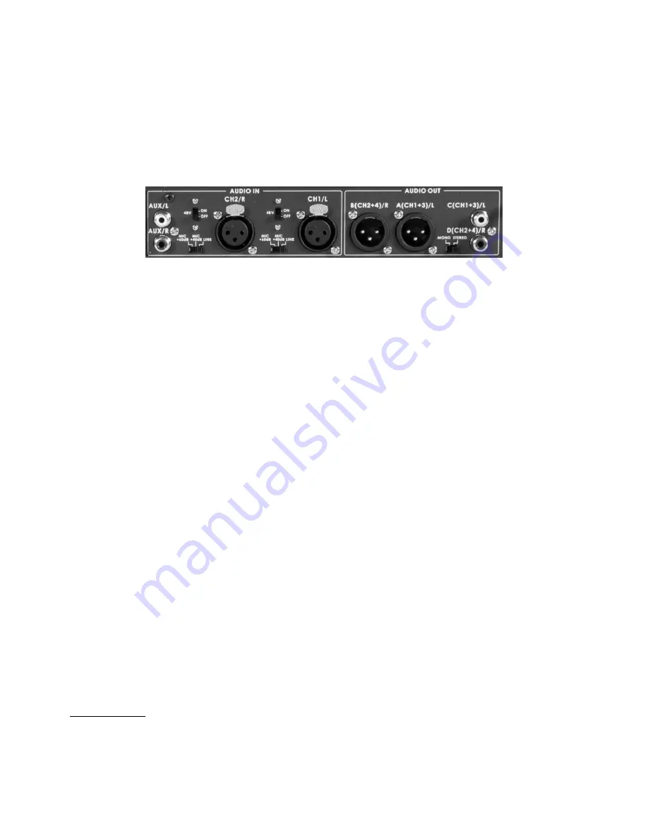
The audio is fed into the mixer on the rear panel using the connections as shown below. 


Line level and Mic level 

Audio  signals  are  fed  into  the  HS-600

’s  audio  mixer  on  standard  analogue  audio  cabling  and  connections. 

Depending on the  audio source, cable  type and settings used these audio source signals can be received  by the 
HS-600  at  different  levels,  typically  Line  level  or  Mic  (microphone)  level.  This  could  be  an  issue  because  audio 
signals which are either too low or too high can ruin an otherwise professional video production or recording.  
 
The main cause of different audio levels being input is usually the source equipment being used. A microphone, a 
CD player, a musical instrument, a DVD player and even a P.A. system can all supply different default audio signal 
levels. So knowing which sources supply stronger or weaker audio signals can help you avoid problems.  
 
Typically  the  industry  uses  the 

Decibel

,  noted  as  two  letters 

dB

,  to  describe  or  measure  the  audio  signal  level 

being supplied by any piece of audio equipment or instrument. Depending on the type of equipment being used the 
letters dB may also  be followed by a further letter indicating  which scale or method of measurement was used to 
rate the signal. Yes, to confuse matters audio levels can be rated or defined using different methods. Luckily, there 
is an easy way to decide which items of kit should supply the lowest and highest signal levels. 
 

Microphones

  -  Typically  supply  the  lowest  audio  signal  levels,  especially  if  they  are  non-powered  microphones. 

There are exceptions to this but as a general rule most microphones will have to be pre-amplified to a higher signal 
level before their audio can be mixed alongside other audio sources. The HS-600 has two mic pre-amp circuits. 
 

Musical  Instruments


– Such as keyboards and guitars supply higher than microphone  signal levels but may still 

need  to  be  pre-amplified  correctly  before  their  audio  can  be  mixed  alongside  other  audio  sources.  Audio  cabling 
used incorrectly can also a

ffect the ‘sound envelope’ of an instrument but we will not go into that here! 


Equipment  with  RCA  or  Phono  Connectors


–  Such  as  CD  players  and  DVD  players  will  supply  audio  at  an 

industry  agreed  ‘default’  line  level  as  there  is  usually  no  way  to  adjust  the  audio  signal  level  going  out  of  the 
equipment. Typically this ‘Line level’ audio is considered to be for delivery to other consumer type equipment such 
as a television set or Hi-Fi equipment, which  will then control the audio  heard at any attached speakers. As such 
this line level (-10dB) is usually much higher than a microphone level and slightly higher than a musical instrument 
signal level. 
 

Equipment  with  balanced  XLR  3  pin  connectors


– Such as professional audio mixers, recorders, players and 

amplifiers  will  supply  audio  at  an  industry  agreed  line  level  too.  The  main  difference  here  is  the  professional  line 
level  can  be  as  much  as  30dB  higher  than  the  consumer  rated  RCA  type  line  level  connection  from  say  a  DVD 
player. That can be very loud and even ear damaging if you are not careful.  
 

SAFETY  FIRST:

 Always connect any audio connections with the  equipment powered off and set the audio mixer 

faders  or  any  headset  volume  knobs  to  minimum.  Then  turn  on  the  equipment  before  slowly  raising  the  audio 
faders or headset volume to a desired comfortable level. 

Summary of Contents for HS-600

Page 1: ...Mobile Video Studio HS 600 SE 600 ITC 50 TLM 170H Instruction Manual www datavideo tek com...

Page 2: ...Main Source and Sub Source Rows 13 BG 13 PIP 13 FZ 13 FTB 13 PVW 13 CUT 13 TAKE 13 T Bar 13 Keyboard Controls Video Transitions 14 Transition Selection 14 Speed Level Selection 14 Keyboard Controls Vi...

Page 3: ...ared PIP to the Program output 22 CG LUMA KEY function 23 Luma Key Setting 23 Choose your LUMA KEY sources 23 KEY level and Transparency 23 Setting up a Luma Key overlay with PowerPoint 24 How to set...

Page 4: ...Monitor 44 RS 422 Protocol 47 Dimensions 47 HS 600 Switcher Specification 48 ITC 50 Specification 49 ITC 100SL Specification 49 Monitor Specification 49 Service and Support 50 Disclaimer of Product an...

Page 5: ...that the total of the ampere ratings on the products plugged into the extension cord do not exceed the extension cord rating 10 Make sure that the total amperes of all the units that are plugged into...

Page 6: ...contact your local Datavideo office or authorized Distributors Certain parts with limited lifetime expectancy such as LCD Panels DVD Drives Hard Drives are only covered for the first 10 000 hours or...

Page 7: ...V Phantom Power switch Two RCA Phono Aux Audio Line level inputs Outputs Multi Image Preview with Video Sources AUX1 AUX2 Preview and Program images Multi Image Preview includes menu selection area co...

Page 8: ...lid slide the thumb catches in the direction shown to their outer most position Then lift the monitor lid upwards away from the keyboard and carry handle The rear connections cover needs to be remove...

Page 9: ...5 Headphone socket 6 3 mm 6 Headphone audio selection for items 5 7 7 Headset 3 5mm socket for ITC 50 8 SDHC Card Slot for firmware and logos 9 Transition selection 10 Effects and Menu selection 11 L...

Page 10: ...on XLR inputs Rear Panel Connections ITC 50 Belt Pack 5pin XLR connectors These eight connectors can each be connected by a cable to a ITC 50 belt pack Optional DV and SDI output board This board sup...

Page 11: ...using a cable with a cross sectional area of at least 1 0 mm2 AUDIO OUT Supports two XLR Balanced Audio outputs Two RCA Phono audio output are also provided User can select mixed Mono or Stereo outpu...

Page 12: ...One for the Preview PST_SUB and one for the Program PGM_MAIN outputs In between the PST and PGM images is the HS 600 Status Display and below it the Settings Display When the Settings Menus are not in...

Page 13: ...e page 19 FZ Freeze The current PST or PGM image displayed is frozen until toggled off FTB Fade To Black This is on the Main Source Rail only Pressing FTB will fade the PGM output to black To fade bac...

Page 14: ...Centre Vertical Wipes from Centre to Left and Right sides Vertical Wipes from Left and Right sides to Centre Corner Wipe from Top Left to Bottom Right Corner Wipe from Bottom Right to Top Left Corner...

Page 15: ...dow B W Press the B W Key to activate the black and white effect USER 1 USER 2 Press the USER 1 Key to select PIP1 BG PIP source Press the USER 2 Key to select PIP2 BG PIP source BG CLR You can select...

Page 16: ...ze a new video frame please press F1 button unlock last frame picture F2 Item by item reset function AUX Source Selection There are four Composite Auxiliary outputs on the rear of the HS 600 Two AUX1...

Page 17: ...row buttons to highlight the COUNT_DOWN_TIME value Use the up or down arrow buttons to change the value 00 00 59 59 Press the ENTER button to confirm the value Use the arrow buttons to highlight ESCAP...

Page 18: ...irm the selection You are presented with four choices The video INPUT adjustment function is described from page 28 The video OUTPUT choices are described from page 29 How to ASSIGN VIDEO SOURCES is d...

Page 19: ...ETTING See page 37 for more information SPEED KEY SETTING adjustment range from 2 to 90 Frames SWITCH BRIGHTNESS adjust keyboard back light brightness 9 STORE RECALL UPDATE Press the SETTING button an...

Page 20: ...ayers when enabled In some setups the PIP 1 image can hide the PIP 2 image Change the position or size of the PIP 1 or PIP 2 image if required The CG LUMA KEY layer can occupy the whole screen If set...

Page 21: ...ow you to change the highlighted the value of the selected option Press the ENTER key to store your chosen value You can choose any of the live video sources from inputs 1 to 8 or the currently define...

Page 22: ...lay PIP_2 on top of your chosen background video press the PIP 2 ENABLE button to toggle it ON or OFF You now need to decide if you are happy with the position and size of PIP_1 or PIP_2 windows You m...

Page 23: ...Menu appear in the Multi Image Preview in between the PST and PGM images The LUMA KEY options provided here are LUMA KEY SETTING 1 SOURCE CH_8 2 KEY LEVEL MAX 240 OFF WHITE 3 KEY LEVEL MIN 20 OFF BLA...

Page 24: ...ot see the computer output then extend the PC s desktop within Windows to monitor 2 as below 6 PC screen size for monitor 2 should match 1280x1024 or 1024x768 7 If HS 600 input 8 is just a blue screen...

Page 25: ...tion Overview The HS 600 can display one or two logos in any location on the screen If you want a larger logo it is possible to create two halves and combine them on the screen The logos when activate...

Page 26: ...GO POSITION X 10 Y 7 3 KEY LEVEL MAX 240 OFF WHITE 4 KEY LEVEL MAX 20 OFF BLACK 5 TRANSPARENT PT 20 W B 6 TRANSPARENCY 0 7 WINDOW LEFT_TOP X 000 Y 000 8 WINDOW RIGHT_BOTTOM X 720 Y 576 9 COPY LOGO FIL...

Page 27: ...KEY function or with the Logo function The benefit of using the Logo function for Luma keying is that you can have two overlays running at the same time over the same video background One overlay cou...

Page 28: ...M images on the Multi Image Preview output This menu option allows the user to change settings which effect video coming into or going out of the HS 600 Use the arrow buttons to highlight the VIDEO IN...

Page 29: ...they are stored within the system so it may only be necessary to make these changes once When the SETTING button is pressed in the EFFECTS area of the HS 600 keyboard the Main Menu list shown left is...

Page 30: ...sary to make these changes once When the SETTING button is pressed in the EFFECTS area of the HS 600 keyboard the Main Menu list shown left is displayed between the PST and PGM images on the Multi Ima...

Page 31: ...ted or defined using different methods Luckily there is an easy way to decide which items of kit should supply the lowest and highest signal levels Microphones Typically supply the lowest audio signal...

Page 32: ...volume knobs to minimum Then turn on the equipment before slowly raising the audio faders or headset volume to a desired comfortable level 48V Switch Phantom power The HS 600 also has the ability to...

Page 33: ...RCA or Master output Repeated presses of the Audio Monitor button cycle an LED through the monitoring choices just above the Audio Peak Meter In many cases headphones will be a more useful and accura...

Page 34: ...0 18 7 CH2 GAIN 0 dB 8 AUX GAIN 0 dB NEXT PAGE Delaying audio to re sync video Video is delayed longer in the mixing process because more data is required to create the image If video effects like Lum...

Page 35: ...e right Pressing the arrow up or arrow down buttons will toggle the selected audio channel ON or OFF for that particular video selection So in our example with the A V button ON and using the above au...

Page 36: ...ratio of all image windows in the Multi Image preview The user can choose between 4 3 and 16 9 2 BORDER BRIGHT This option allows the user to adjust the brightness of the border of all image windows...

Page 37: ...yourself or purchased Please speak with your Dealer or local Datavideo office to get further help and advice 1 COUNT_DOWN_TIME 2 PIP 3 CG LUMA KEY 4 LOGO 5 VIDEO IN OUT 6 AUDIO MIXER 7 MULTI IMAGE 8...

Page 38: ...ING 2 UPDATE FIRMWARE 3 RESET ALL Press key 2 SEC ESCAPE 3 RESET ALL Press key 2 SEC This reset option allows the user to clear any current settings and return to the mixers factory default values It...

Page 39: ...to the formatted empty SDHC card 4 Insert the SDHC card into the SD card slot on the front edge of the HS 600 keyboard 5 Turn on the HS 600 and the unit will start normally 6 Now enter the SETTINGS m...

Page 40: ...ture card or a computer SDI CG overlay card or a Satellite transmission link SDI signals from this card can be sent over standard SDI 75 Ohm BNC cabling for 100m before needing to be re clocked A Data...

Page 41: ...the HS 600 otherwise you may damage the USB Socket Light and Monitor XLR Microphone Socket Combined XLR 6 3mm Jack Microphone Input for either a Condenser or Dynamic Gooseneck Microphone If a headset...

Page 42: ...the volume of the attached headphones It also controls the level for the mic and paging tone heard when the belt pack is called Mic Headphone Socket The ITC 100SL has both 3 5mm and 2 5mm Mic Headset...

Page 43: ...XLR Cable is a straight through cable pin 1 to pin 1 pin 2 to pin 2 etc ITC 100SL Belt pack 3 5mm Jack socket Headset connector Please Note For connecting a professional headset Datavideo can supply...

Page 44: ...of an input is displayed on the screen This allows adjustments of chroma and phase Phase adjustment is effective with NTSC signals PATTERN Press this button to display the monitors built in SMPTE colo...

Page 45: ...llow the same steps as described for brightness above PIP Feature Setting To access the menu press ENTER so that PIP Mode is highlighted To access the options for the selected setting press ENTER agai...

Page 46: ...choose Frame Ratio Off 80 90 4 3 Mark Line On Off Scan Mode Underscan Over Scan Central Mark On Off Cinema Zone Mark On Off Mask Type Overlay Transparent NOTE Frame Ratio This will display a Safe Are...

Page 47: ...o that Factory Reset is highlighted and then press ENTER again to highlight the option Use the UP Down button to select YES from the options and then press ENTER to reset the monitor After a few secon...

Page 48: ...Frame still store memory as a source SMPTE pattern out or selected colour background Preview output 1 x DVI D for Multi Viewer with countdown timer and audio level indicator Resolution is 1920x1080p...

Page 49: ...set Impedance 8 600 ohms 100mW min Microphone Level 67Db or 2 5mm Stereo Jack Socket for Motorola Mobile Phone type headset microphone TALLY OUT SOCKET 3 5mm Jack Socket to connect to TD 1 Tally Indic...

Page 50: ...851 000 Fax 44 1457 850 964 E Mail sales datavideo co uk Datavideo Technologies Co Ltd Tel 886 2 8227 2888 Fax 886 2 8227 2777 E mail service datavideo com tw Datavideo Technologies China Co Ltd Tel...

Reviews: