________________________________________________________
__
Page - 36
Setup and Self Test
3.9 Selecting the Mode
After the mode of operation is determined, the function switch on the
back of the Printer can be changed to select the desired mode. Turn the
Printer OFF while making changes to the switch settings (function
switches are only read during power-up).
SW1-5
STANDARD INPUT
OFF
STAND-ALONE BATCH
ON
3.10 Using Standard Input Mode
For most applications, the interface between the Printer and the host
device will be RS-232C. The cable needed to connect the Printer to the
host will be either a straight through or null modem cable. This cable
connects the DB-25 connector labeled J2 on the back of the Printer to
the serial data connector on the host device.
Several cables for typical interfaces are listed in Appendix C. The pin
configuration of the Printer for most descriptions of the RS-232
interface on a DB-25 connector is DTE (Data Terminal Equipment), that
is, pin 2 is transmit, 3 is receive, and 7 is ground.
The Printer supports both XON/XOFF and CTS/DTR handshaking.
Whenever the Printer is interfaced in a mode that will be using
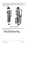
XON/XOFF, a jumper must be placed between pins 5 and 4 to enable
the operation of the Printer's transmit line.
For connection to most host systems, the XON/XOFF handshaking
works to reduce the number of wires needed in the interface cable. For
interfacing RS-422 devices, the XON/XOFF handshake is the only
appropriate method.
Summary of Contents for Prodigy
Page 1: ...Prodigy Operator s Manual ...
Page 3: ......
Page 4: ......
Page 8: ......
Page 54: ...________________________________________________________ __ Page 46 Using the Printer ...
Page 84: ...________________________________________________________ __ Page 76 Using the Printer ...
Page 125: ...Appendix D Page D 9 6 Continued 152 DPI Printer ...
Page 140: ......
Page 142: ...Page E 2 Appendix E ...
Page 146: ...4 Warranty Information ...


