


Disconnecting wires from the control terminals
1.
To open the contact, insert a small screwdriver
into the slot between the terminal holes and
push the screwdriver inward.
2.
Pull gently on the wire to free it from the control
terminal contact.
See
chapter 10.5 Cable Specifications
for control terminal
wiring sizes and
chapter 8 Wiring Configuration Examples
for
typical control wiring connections.
5.9.4 Enabling Motor Operation
(Terminal 27)
A jumper wire is required between terminal 12 (or 13) and
terminal 27 for the drive to operate when using factory
default programming values.
•
Digital input terminal 27 is designed to receive
24 V DC external interlock command.
•
When no interlock device is used, wire a jumper
between control terminal 12 (recommended) or
13 to terminal 27. This wire provides an internal
24 V signal on terminal 27.
•
When the status line at the bottom of the LCP
reads
AUTO REMOTE COAST
, the unit is ready to
operate, but is missing an input signal on
terminal 27.
•
When factory-installed optional equipment is
wired to terminal 27, do not remove that wiring.
NOTICE
The drive cannot operate without a signal on terminal
27, unless terminal 27 is reprogrammed using
parameter 5-12 Terminal 27 Digital Input
.
5.9.5 Configuring RS485 Serial
Communication
RS485 is a 2-wire bus interface compatible with multi-drop
network topology, and it contains the following features:
•
Either Danfoss FC or Modbus RTU communication
protocol, which are internal to the drive, can be
used.
•
Functions can be programmed remotely using
the protocol software and RS485 connection or in
parameter group 8-** Communications and
Options
.
•
Selecting a specific communication protocol
changes various default parameter settings to
match the specifications of the protocol, making
more protocol-specific parameters available.
•
Option cards for the drive are available to provide
more communication protocols. See the option
card documentation for installation and operation
instructions.
•
A switch (BUS TER) is provided on the control
card for bus termination resistance. See
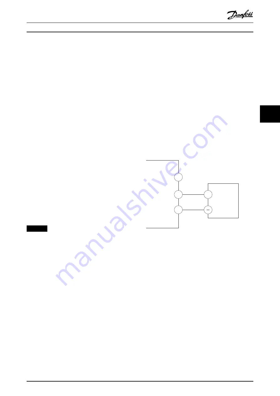
For basic serial communication set-up, perform the
following steps:
1.
Connect RS485 serial communication wiring to
terminals (+)68 and (-)69.
1a
Use shielded serial communication cable
(recommended).
1b
See
chapter 5.4 Connecting to Ground
for
proper grounding.
2.
Select the following parameter settings:
2a
Protocol type in
parameter 8-30 Protocol
.
2b
Drive address in
parameter 8-31 Address
.
2c
Baud rate in
parameter 8-32 Baud Rate
.
61
68
69
+
130BB489.10
RS485
Illustration 5.39 Serial Communication Wiring Diagram
5.9.6 Wiring Safe Torque Off (STO)
The Safe Torque Off (STO) function is a component in a
safety control system. STO prevents the unit from
generating the voltage required to rotate the motor.
To run STO, more wiring for the drive is required. Refer to
Safe Torque Off Operating Guide
for further information.
5.9.7 Wiring the Space Heater
The space heater is an option used to prevent conden-
sation from forming inside the enclosure when the unit is
turned off. It is designed to be field wired and controlled
by an external system.
Specifications
•
Nominal voltage: 100–240
•
Wire size: 12–24 AWG
Electrical Installation
Operating Guide
MG34U502
Danfoss A/S © 09/2018 All rights reserved.
65
5
5
Summary of Contents for VLT AutomationDrive FC 302
Page 2: ......