


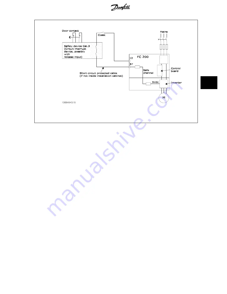
Illustration 5.38: Illustration of the essential aspects of an installation to achieve a Stopping Category 0 (EN 60204-1) with safety Cat. 3 (EN
954-1).
5.7.2 Safe Stop Commissioning Test
After installation and before first operation, perform a commissioning test of an installation or application making use of FC 200 Safe Stop.
Moreover, perform the test after each modification of the installation or application, which the FC 200 Safe Stop is part of.
The commissioning test:
1.
Remove the 24 V DC voltage supply to terminal 37 by the interrupt device while the motor is driven by the FC 202 (i.e. mains supply is not
interrupted). The test step is passed if the motor reacts with a coast and the mechanical brake (if connected) is activated.
2.
Then send Reset signal (via Bus, Digital I/O, or [Reset] key). The test step is passed if the motor remains in the Safe Stop state, and the
mechanical brake (if connected) remains activated.
3.
Then reapply 24 V DC to terminal 37. The test step is passed if the motor remains in the coasted state, and the mechanical brake (if connected)
remains activated.
4.
Then send Reset signal (via Bus, Digital I/O, or [Reset] key). The test step is passed if the motor becomes operational again.
5.
The commissioning test is passed if all four test steps are passed.
5.8 Additional Connections
5.8.1 Relay Output
Relay 1
•
Terminal 01: common
•
Terminal 02: normal open 240 V AC
•
Terminal 03: normal closed 240 V AC
Relay 2
•
Terminal 04: common
•
Terminal 05: normal open 400 V AC
•
Terminal 06: normal closed 240 V AC
Relay 1 and relay 2 are programmed in par. 5-40
Function Relay
, par.
5-41
On Delay, Relay
, and par. 5-42
Off Delay, Relay
.
Additional relay outputs by using option module MCB 105.
VLT
®
AQUA Drive Design Guide
5 How to Install
MG.20.N5.02 - VLT
®
is a registered Danfoss trademark
149
5