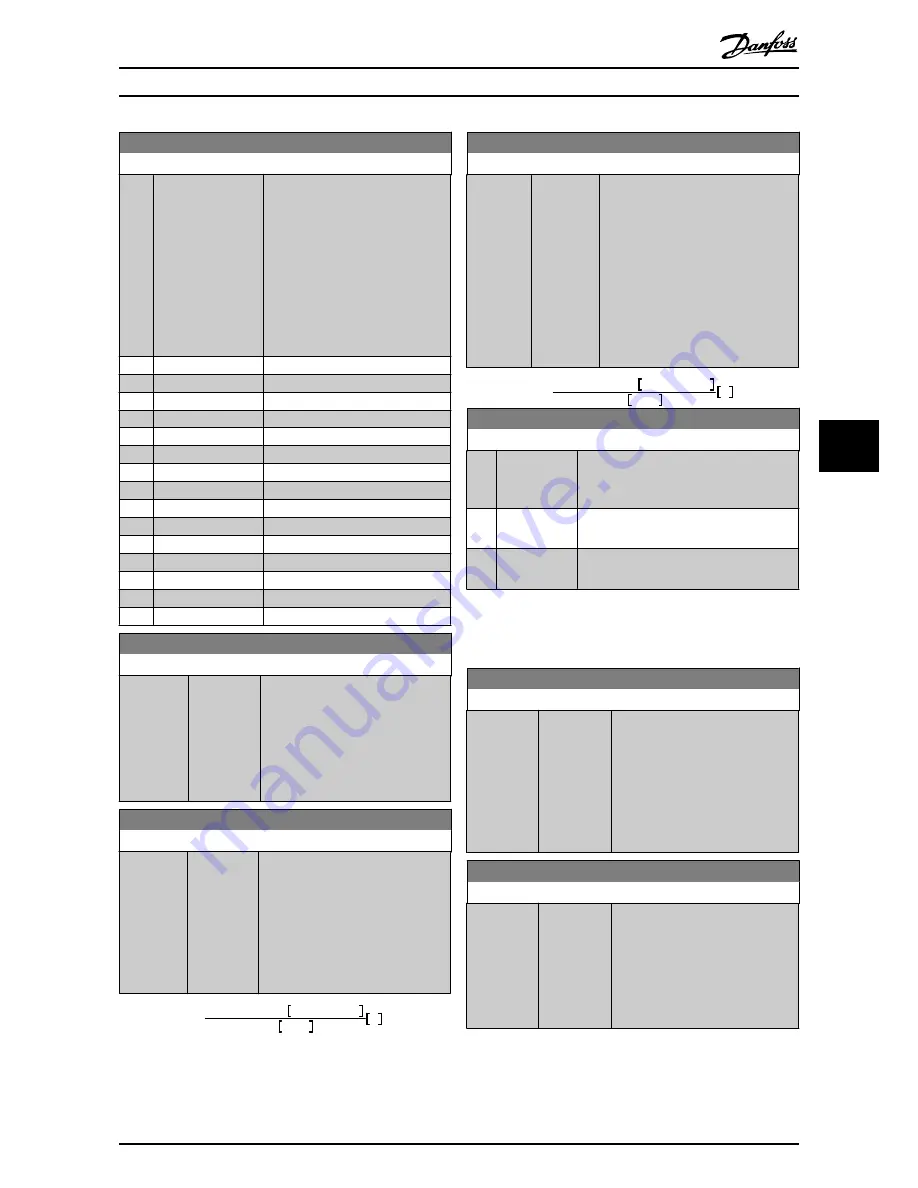
3-16 Reference 2 Source
Option:
Function:
Select the reference input to be used
for the second reference signal.
par. 3-15
Reference 1 Source
,
par. 3-16
Reference 2 Source
and
par. 3-17
Reference 3 Source
define up
to three different reference signals.
The sum of these reference signals
defines the actual reference.
This parameter cannot be adjusted
while the motor is running.
[0]
No function
[1]
Analog input 53
[2]
Analog input 54
[7]
Pulse input 29
[8]
Pulse input 33
[20]
*
Digital pot.meter
[21]
Analog input X30/11
[22]
Analog input X30/12
[23]
Analog Input X42/1
[24]
Analog Input X42/3
[25]
Analog Input X42/5
[29]
Analog Input X48/2
[30]
Ext. Closed Loop 1
[31]
Ext. Closed Loop 2
[32]
Ext. Closed Loop 3
3-19 Jog Speed [RPM]
Range:
Function:
Application
dependent
*
[Application
dependant]
Enter a value for the jog speed n
JOG
,
which is a fixed output speed. The
frequency converter runs at this
speed when the jog function is activa-
ted. The maximum limit is defined in
par. .
See also par. 3-80
Jog Ramp Time
.
3-41 Ramp 1 Ramp Up Time
Range:
Function:
Application
dependent
*
[Applica-
tion
dependant]
Enter the ramp-up time, i.e. the
acceleration time from 0 RPM to
par. 1-25
Motor Nominal Speed
. Choose
a ramp-up time such that the output
current does not exceed the current
limit in par. 4-18
Current Limit
during
ramping. See ramp-down time in
par. 3-42
Ramp 1 Ramp Down Time
.
par
.3
−
41 =
t
acc
×
n
norm
par
.1
−
25
ref
rpm
s
3-42 Ramp 1 Ramp Down Time
Range:
Function:
Application
depend-
ent
*
[Applica-
tion
dependant]
Enter the ramp-down time, i.e. the
deceleration time from par. 1-25
Motor
Nominal Speed
to 0 RPM. Choose a
ramp-down time such that no over-
voltage arises in the inverter due to
regenerative operation of the motor,
and such that the generated current
does not exceed the current limit set in
par. 4-18
Current Limit
. See ramp-up
time in par. 3-41
Ramp 1 Ramp Up
Time
.
par
.3
−
42 =
t
dec
×
n
norm
par
.1
−
25
ref
rpm
s
4-10 Motor Speed Direction
Option:
Function:
Selects the motor speed direction required.
Use this parameter to prevent unwanted
reversing.
[0]
Clockwise
Only operation in clockwise direction will be
allowed.
[2]
*
Both directions Operation in both clockwise and anti-
clockwise direction will be allowed.
NOTE
The setting in par. 4-10
Motor Speed Direction
has impact
on the Flying Start in par. 1-73
Flying Start
.
4-11 Motor Speed Low Limit [RPM]
Range:
Function:
Application
dependent
*
[Application
dependant]
Enter the minimum limit for motor
speed. The Motor Speed Low Limit
can be set to correspond to the
manufacturer’s recommended
minimum motor speed. The Motor
Speed Low Limit must not exceed
the setting in par. 4-13
Motor Speed
High Limit [RPM]
.
4-12 Motor Speed Low Limit [Hz]
Range:
Function:
Application
dependent
*
[Application
dependant]
Enter the minimum limit for motor
speed. The Motor Speed Low Limit
can be set to correspond to the
minimum output frequency of the
motor shaft. The Speed Low Limit
must not exceed the setting in
par. 4-14
Motor Speed High Limit [Hz]
.
How to Programme the Frequ...
VLT
®
HVAC Drive Operating Instructions
MG.11.AD.02 - VLT
®
is a registered Danfoss trademark
75
7
7


