background image

Danfoss ET4000 Crimp Machine Operator’s Manual

AQ439269047772en-000101

© Danfoss ET4000 Crimp Machine Operator’s Manual | 2023.02. | 5

Shop/Work Table Mounting

Instructions for Shop/Work Table Mounting 

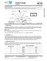
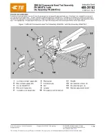
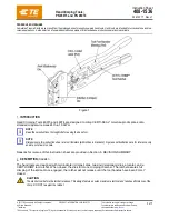
Figure 1 - Bench Layout for ET4000 Press

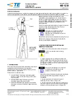
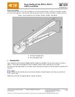
Figure 2 - Lifting Hole Layout on ET4000 Press Top Plate

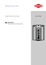
Figure 3 - T-441 Outlet Port

The following methods are offered as a guide and may be varied to suit 
your particular needs.

1. 

Prepare mounting surface for ET4000 press and pump. Refer to FIGURE 
1 for bolt hole layout and optimum height.

IMPORTANT: 

Care must be taken to insure that the surface to which 

the press is bolted is capable of supporting the weight of the press 
(approximately 500 lbs.) and pump which is 75 lbs.

2. 

Remove shipping carton from ET4000 press. There are four 5/8-18 
tapped hoes in top plate which may be used for lifting purposes (see 
FIGURE 2). If these tapped holes are used, it is recommended that a 
minimum of two be utilized, preferably four. If two holes are used for 
lifting, use holes directly across from each other on the center line and 
not two on a diagonal. This will prevent press from tilting as it is raised.

3. 

Using an adequate lifting device, raise the press to the mounting 
surface. Align holes in press support brackets with holes in mounting 
surface. Insert four 1/2” bolts from top of mounting surface. Washers 
and nuts are installed from underneath. TIGHTEN.

4. 

Place the T-441 pump on the mounting surface to the right and 
slightly behind the ET4000 press. (Reference FIGURE 4, Page 6)

5. 

Mark power unit base plate hole pattern on mounting surface. 
Remove power unit and drill holes.

6. 

Replace pump and align holes on mounting surface with base plate of 
pump. Insert bolts from top of mounting surface. Washers and nuts are 
installed from underneath. TIGHTEN.

7. 

Remove middle plug from outlet port in pump. (See FIGURE 3.)

8. 

Locate press/pump connecting hose assembly and remove plugs. 
Connect unions into outlet port in pump and press. TIGHTEN.

9. 

Remove pipe plug from pump reservoir and replace with breather cap 
provided.

10.  Before the electric pump (T-441) can be activated, the interlock cord 

must be plugged into the switch box mounted on the ET4000 crimper. 
After mating the halves of connection, TIGHTEN the knurled nut.

11.  Plug electric cord into a grounded (4-wire connection), 220 volt, 60 

cycle, single phase outlet. IT IS RECOMMENDED THAT THE PUMP BE ON 
AN INDIVIDUAL 15 AMP SERVICE OUTLET.

Summary of Contents for ET4000

Page 1: ...Operator s Manual Danfoss ET4000 Crimp Machine...

Page 2: ...Table of Contents Safety Instructions 3 Specifications and equipment 4 Shop work table mounting 5 Check out procedure 6 Operating instructions ET4000AR 001 7 Operating instructions ET4000AR 002 8 9 O...

Page 3: ...recommended nor authorized by Danfoss Safety Instructions 1 PREVENT UNAUTHORIZED OPERATION Do not permit anyone to operate this equipment unless they have read and thoroughly understand this manual 2...

Page 4: ...s ideally suited for use with the ET4000 press It features a two stage pump providing high flow at low pressure for fast ram approach and low flow at high pressure for actual crimping Dimensions 7 1 2...

Page 5: ...m tilting as it is raised 3 Using an adequate lifting device raise the press to the mounting surface Align holes in press support brackets with holes in mounting surface Insert four 1 2 bolts from top...

Page 6: ...s required use ISO 32 SAE 10W WARNING Dot not cycle without base adapter ring in place Check out procedure for using electric pump T 441 1 Plug electric cord into a grounded 4 wire connection 220 volt...

Page 7: ...of the collet assembly with a high efficiency PTFE based lubricant 2 INSERT the hose assem bly through the bottom of the base adapter ring and between the two collet assembly halves Align the fitting...

Page 8: ...2 PULL the pusher knob upward The pusher knob is located behind the top of the pushers near the back of the machine 3 SLIDE pushers to side while holding the pusher knob up 4 PULL spacer ring locator...

Page 9: ...he two collet assembly halves Align the fitting with the top of the collet halves as referenced in the PowerSource Crimp Spec tool at danfoss com crimp 9 CLOSE the pusher halves and begin crimping by...

Page 10: ...the inside cone of the base adapter ring and external surfaces of the collet assembly with a high efficiency PTFE based lubricant 3 SELECT proper size collet referenced in the PowerSource Crimp Spec t...

Page 11: ...al hose assembly procedure To insure a proper crimp diameter reading follow these steps 1 Measure the diameter in the middle of the crimped portion of the hose end 2 Place the caliper in a position to...

Page 12: ...stuck open Replace pump Motor runs Pusher advances but doesn t Pump unload valve stuck shut Replace Pump develop final crimp pressure blows fuse Motor runs Pusher advances but doesn t Relief valve lea...

Page 13: ...uge in place operate unit to full crimping position Gauge should read approximately 5000 PSI To raise setting turn screw inward clockwise to lower turn screw outward counter clockwise in 1 4 turn incr...

Page 14: ...00101 Repair and Replacement Items ITEM NUMBER QTY PART NUMBER DESCRIPTION 1 1 T 410 1M Micro Switch 2 1 ET4000AR 001 Base Adapter Ring 3 1 ET4000AR 002 Base Adapter Ring 4 1 ET4000TP 001 Locator Brac...

Page 15: ...Danfoss ET4000 Crimp Machine Operator s Manual AQ439269047772en 000101 Danfoss ET4000 Crimp Machine Operator s Manual 2023 02 15...

Page 16: ...ss hoses fittings and tooling provide the ultimate fluid conveyance solutions for a variety of equipment and applications around the world We proudly engineer to support a sustainable future for tomor...

Reviews: