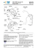


Instruction Sheet
1 of 19
© 2023 TE Connectivity Ltd. family of companies.
All Rights Reserved.
TE Connectivity, TE connectivity (logo), and TE (logo) are trademarks. Other logos, product, and/or company names may be trademarks of their respective owners.
PRODUCT INFORMATION 1-800-522-6752
This controlled document is subject to change.
For latest revision and Regional Customer Service,
visit our website at
408-1261
28 FEB 2023 Rev L
Proper use guidelines
Cumulative trauma disorders can result from the prolonged use of manually powered hand tools. Hand tools are intended for occasional
use and low-volume applications. A wide selection of powered application equipment is available for extended-use production operations.
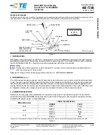
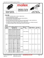
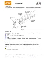
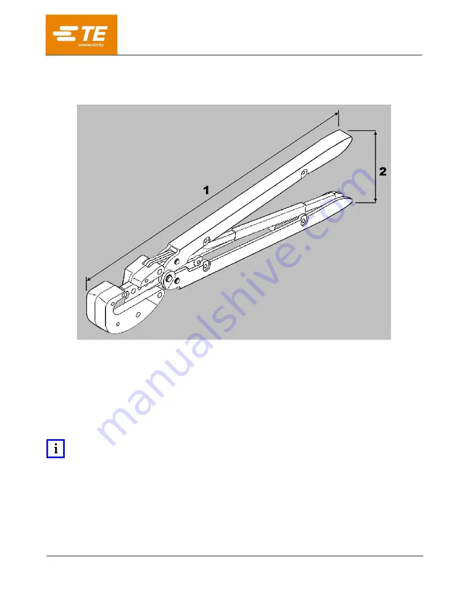
Figure 1: Heavy Head Hand Tools 59239-4, 59239-8, 59287-2, and 525692
1
304.8 [12.00] approximate
2
76.2 [3.00] approximate
1 Introduction
Heavy Head Hand Tools (HHHT) 525692, 59239-4, 59239-8, and 59287-2 are the tool and die set shown in
Figure 1. These tools are designed to crimp the product listed in Table 1 onto the wire also listed.
For other tools accompanied by this instruction sheet, follow the instructions for the tool used to crimp the same
wire size.
NOTE
Dimensions in this instruction sheet are in millimeters with [inches in brackets]. Figures are for reference only and are not
drawn to scale.
Read these instructions thoroughly before crimping connectors.
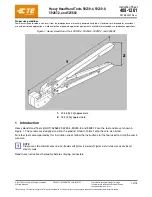
Heavy Head Hand Tools 59239-4, 59239-8,
59287-2, and 525692