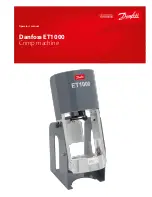
Danfoss ET4000 Crimp Machine Operator’s Manual
AQ439269047772en-000101
© Danfoss ET4000 Crimp Machine Operator’s Manual | 2023.02. | 13
Troubleshooting Procedures
Troubleshooting Danfoss T-441 Electric Pump
IMPORTANT:
Pressure must
be relieved from system before
disconnecting hose, installing
gauge or removing valves from
pump
Step 1:
Look for fuse, loose wire
connections, switch malfunctions
or damaged cord. Check for proper
installation of a 220 volt circuit.
Step 2:
Check oil level - after
assembly and system has been
purged of air, the fluid level should
be 1/2” from top of reservoir.
Clean, anti-wear type, having
a 300 SSU/100˚ hydraulic oil is
recommended (ISO 32 or SAE 10W).
Oil is needed to:
1.
Transmit power easily through
system
2.
Lubricate moving parts
3.
Provide seal clearances
between parts
4.
To cool or dissipate heat
Step 3:
Clean or reset relief valve - a
6000 PSI pressure gauge, a 5/16”
Allen wrench, a 1” socket and a
screwdriver are required. Remove
cap from relief valve. Remove
adjustment screw, spring and ball.
Ball should be attached to spring.
Check ball and seat for possible
scoring.
Replace spring and ball in cavity.
Insert a small punch through spring
against ball. Give punch a moderate
tap to seat ball. Return adjustment
screw to original position making
sure adjustment screw is at least
one turn from bottoming. Remove
1/4” NPTF plug from port above
check valve and install a 6000
PSI pressure gage. With 6000 PSI
pressure gauge in place, operate
unit to full crimping position. Gauge
should read approximately 5000
PSI. To raise setting, turn screw
inward (clockwise); to lower, turn
screw outward (counter-clockwise)
in 1/4 turn increments. After each
adjustment, recycle and read gauge
for proper setting.
Run a cycle of the crimping system
for final gauge reading before
removing gauge and reinstalling
pipe plug.
S
tep 4:
Shuttle Valve - If the shuttle
valve is in a closed position and the
ET4000 pusher will not retract, it
may be helpful to tap the shuttle
valve cap several times to dislodge
any silt that may be causing the
stem to bind. If this does not free
the valve and allow the pusher
to retract, use extreme caution
prior to proceeding with shuttle
valve removal as the system is
still under pressure. It may be
advisable to relieve pressure at a
hose connection to avoid an oil
bath. After pressure is removed
from system, remove cap and
valve cartridge. Soak cartridge in a
PETROLEUM BASED SOLVENT ONLY
(clean Stoddard solvent). Do not use
Triethene, Gasoline or Paint Thinner
as they will damage the O-Ring
Seals. If cartridge disassembly is
required use care in removing stem
as it has a .0005 metal seal fit. Rotate
stem in solvent and push from seat
end to remove from cartridge. Do
not lose the loose ball. Wash parts
in clean solvent and examine for
any surface markings. If necessary,
polish with a fine crocus cloth.
After final cleaning, reassembly
cartridge. Shake cartridge and
check for free movement of ball
and stem. Replace cartridge if not
functional at this point. Reassemble
shuttle valve into it’s cavity and
check crimping cycle prior to using
system.