23
1
3
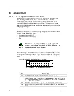
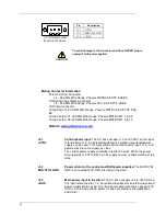
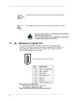
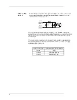
(J1 Connector view
from front of drive).
Pin
Description
J1-1
+CTRL
J1-2
BUS/CTRL GND
J1-3
+BUS
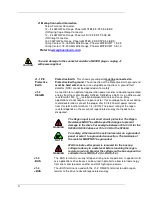
CAUTION
To avoid damage to the connector and drive, NEVER plug or
unplug J1 with power applied.
Mating Connector Information
Screw Terminal Connector
12 – 24 AWG Wire Range, Phoenix MSTB2,5/3-STF-5,08-BK
OR
Spring Cage Clamp Connector
12 – 24 AWG Wire Range, Phoenix FKC 2,5/3-SFT-5,08-BK
OR
Crimp Connector
Crimp Shell: 14-20 AWG Wire Range, Phoenix MSTBC 2,5/3-STZF-5,08-
BK
Crimp Contact: 14-16 AWG Wire Range, Phoenix MSTBC-MT 1,5-2,5
Crimp Contact: 18-20 AWG Wire Range, Phoenix MSTBC-MT 0,5-1,0
Refer to
www.phoenixcon.com
.
J1-1
+CTRL
Control power input. The DC drive a10 to +90 VDC on this input
referenced to J1-2. An isolated regulated or isolated unregulated power
supply can be used. This input can be connected to +Bus input, J1-3, and
powered by the same supply as +Bus.
The control power supply should be rated for 20 watts. While the power
drain typically is 2 W to 8 W, a 20 W supply ensures reliable starting of the
drive.
J1-2
BUS/CTRL GND
Power return for the control and BUS power supplies. The BUS/CTRL
GND is connected to I/O RTN internally in the drive.
J1-3
+BUS
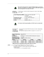
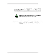
Main power input to the drive. The DC drive a20 to +90 VDC on
this input referenced to J1-2. An isolated regulated or isolated unregulated
power supply can be used. The +Bus power drain with +Bus voltage at 75
VDC is in the range shown below. It varies according to the application
and motor.
Summary of Contents for S20630
Page 6: ......
Page 15: ...9 3 1 6 E 6 E 6 E 6 E 6 E 6 E 6 E 6 E...
Page 19: ...13 1 6 11 General 3H 3 3H 5 E 3 3 5J...
Page 94: ......


