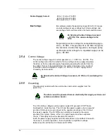
29
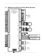
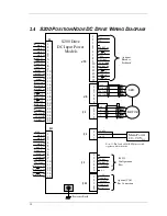
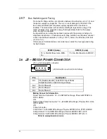
J2-1 PE
Motor Case
Ground
On S200 AC Input Drives this point is connected to Chassis Ground.
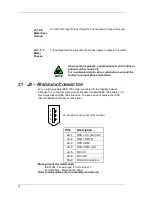
J2-2, 3, 4
Motor
Phases
These three terminals provide the 3-phase power output to the motor.
NOTE
Observe motor polarity, connect phase U on the drive to
phase U on the motor, etc.
For nonstandard motor drive combinations consult the
factory for proper phase orientation.
2.7
J3 – F
EEDBACK
C
ONNECTOR
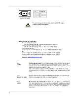
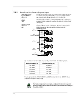
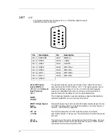
J3 is a 6-pin plugable IEEE 1394 style connector for the feedback device.
Although this connector mechanically accepts standard IEEE 1394 cables, it is
electrically not an IEEE 1394 interface. The base drive accepts either SFD
(Smart Feedback Device) or Hall inputs.
1
2
3
4
5
6
(J3 Connector view from front of drive)
Pins
Description
J3-1
SFD +5 V (200 mA)
J3-2
SFD +5 RTN
J3-3
SFD COM-
J3-4
SFD COM+/CU
J3-5
NC/CV
J3-6
NC/CW
Shell
Shield Connection
Mating Connector Information
IEEE1394, Firewire type, 2.0 mm plug set
22 AWG Max., Molex 55100-0600
Refer to www.molex.com for assembly instructions.
Summary of Contents for S20630
Page 6: ......
Page 15: ...9 3 1 6 E 6 E 6 E 6 E 6 E 6 E 6 E 6 E...
Page 19: ...13 1 6 11 General 3H 3 3H 5 E 3 3 5J...
Page 94: ......


