background image

100  

  Troubleshooting 

Calibir 640 GigE IR Camera User's Manual 


Acquisition Error without Timeout Messages  

Streaming video problems range from total loss of image data to occasional loss of random video 

data packets. The following section describes conditions identified by Teledyne DALSA engineering 

while working with Calibir in various computers and setups. See the Teledyne DALSA Network 

Imaging manual for information on network optimizations.  

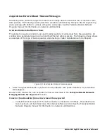
Grab has Random Bad Data or Noise 

The problem is seen as random noise and missing sections of video data from the acquisition. All 

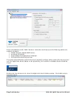
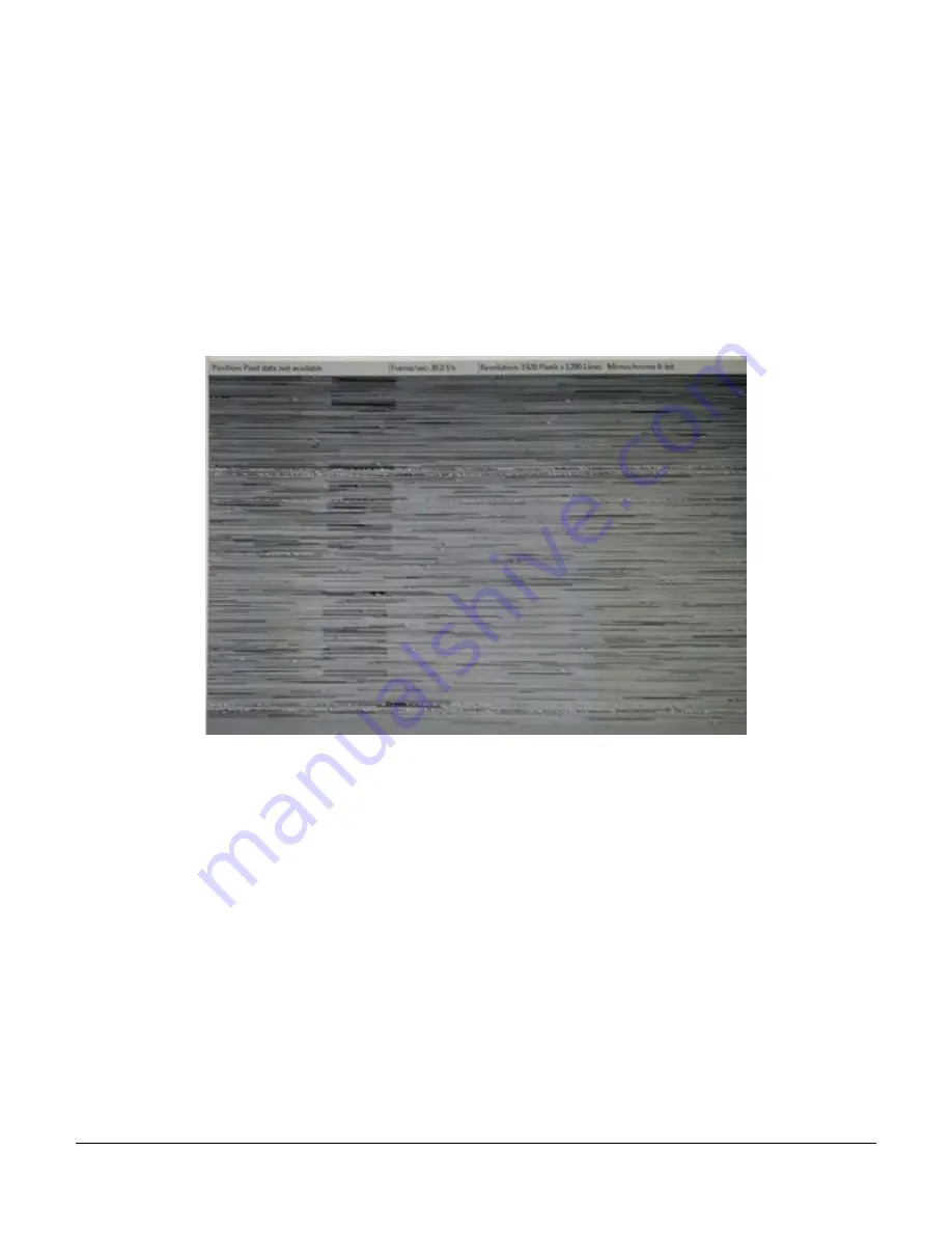
configuration parameters seem correct and the Ethernet cable is secure. The following image shows 

an example of this type of bad acquisition while testing a Calibir installation with CamExpert. 


Figure 50: Random Bad Data or Noise Example 


Some marginal NIC boards or ports can cause problems with packet transfers. Try alternative 

NIC adapters.  

Review other reasons for such acquisition errors as described in the Teledyne DALSA Network 

Imaging Module for Sapera LT manual.  

Camera is functional but frame rate is lower than expected  


Verify Ethernet link speed. If the LAN connection is limited to 100 Mbps, the Calibir frame 

rate maximum will be limited once the internal buffers are filled. See the Teledyne DALSA 

Network Imaging manual for information on network optimizations.  

Summary of Contents for Calibir 640 AB

Page 1: ...CALIBIR 640 GigE IR Camera User s Manual sensors cameras frame grabbers processors software vision solutions July 10 2017 P N IRACUVM USER0 www teledynedalsa com ...

Page 2: ...emarks or intellectual property mentioned herein belong to their respective owners About Teledyne DALSA Teledyne DALSA is an international high performance semiconductor and electronics company that designs develops manufactures and markets digital imaging products and solutions in addition to providing wafer foundry services Teledyne DALSA Digital Imaging offers the widest range of machine vision...

Page 3: ... Fiber Optic Interface Requirements 17 QUICK START GUIDE 18 CONNECTING THE CALIBIR 640 GIGE VISION CAMERA 18 Power Specifications 18 Steps For Camera Startup 18 Calibir 640 GigE Connectors 19 Preventing Operational Faults due to ESD 19 Calibir IP Configuration Sequence 20 CAMERA CONNECTION SETUP 21 Changing the Bit Range to Display 22 FEATURES AND CONFIGURATION OPTIONS 23 HEAT SINKS 24 ADJUSTING T...

Page 4: ...3 GigE Server Status 53 Optimizing the Network Adapter used with Calibir GigE 54 Quick Test with CamExpert Windows 54 About the Device User ID 55 USING CAMEXPERT WITH CALIBIR GIGE CAMERAS 56 CAMERA INFORMATION CATEGORY 59 Camera Information Feature Descriptions 59 Power up Configuration Dialog 62 SENSOR CONTROL CATEGORY 64 Sensor Control Feature Descriptions 64 I O CONTROLS CATEGORY 65 I O Control...

Page 5: ...d the Sensor 94 Protecting Against Dust Oil and Scratches 94 Cleaning the Sensor Window 94 TROUBLESHOOTING 95 OVERVIEW 95 QUICK RECOVERY GUIDE 95 GENERAL TROUBLESHOOTING FOR CALIBIR 640 SERIES 97 Error Log File 97 Power Failure During a Firmware Update Now What 97 Power supply problems 97 Camera is functional but image has no contents 97 CALIBIR 640 GIGE TROUBLESHOOTING 97 GigE Server Status 97 Pr...

Page 6: ...verlay 50 Figure 25 GigE Server Tray Icon 53 Figure 26 GigE Pop up Menu 53 Figure 27 GigE Vision Device Status 54 Figure 28 Sapera CamExpert 55 Figure 29 Sapera CamExpert GUI Layout 57 Figure 30 CamExpert Camera Information Category 59 Figure 31 Power up Configuration Dialog 63 Figure 32 CamExpert Sensor Control Category 64 Figure 33 CamExpert I O Controls Category 65 Figure 34 External In Control...

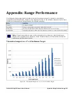
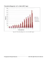
Page 7: ...Figures 7 Figure 49 Ruggedized RJ45 Ethernet cable with Thumbscrews 93 Figure 50 Random Bad Data or Noise Example 100 Figure 51 Theoretical Ranges for a 1 7 x 0 5m Human Target 103 Figure 52 Theoretical Ranges for a 2 3 x 2 3m NATO Target 104 ...

Page 8: ...xamples 43 Table 9 GigE Server Tray Icon States 53 Table 10 CamExpert Display Pane Control Buttons 56 Table 11 Camera Information Feature Descriptions 59 Table 12 Sensor Control Feature Descriptions 64 Table 13 I O Controls Feature Descriptions 65 Table 14 Image Format Controls Feature Descriptions 68 Table 15 Metadata Controls Feature Descriptions 70 Table 16 Image Processing Feature Descriptions...

Page 9: ...e DALSA s Sapera LT SDK Within the Sapera LT SDK we currently offer a generic GigE Vision driver that supports all Teledyne DALSA GigE Vision cameras including all future Calibir GigE Vision cameras The Sapera LT initial version that supports this driver is Sapera LT v7 20 We strongly recommend using v8 10 or Greater for an improved User Experience http www teledynedalsa com imaging support downlo...

Page 10: ...AB M25 lens Mount 29mm x 29mm x 61 13mm with lens mount M34 lens Mount 37 0mm x 37 0mm x 59 26mm with lens mount Mass without lens Calibir 640 Core M25 lens Mount 38g M34 lens Mount 39g Calibir 640 GigE M25 lens Mount 58 4g M34 lens Mount 59 4g Calibir 640 AS M25 lens Mount 48 2g M34 lens Mount 49 2g Calibir 640 AB M25 lens Mount 54 1g M34 lens Mount 55 1g Power connector via Samtec 10 pin connect...

Page 11: ... difference Typ 116mK f 1 298K 30Hz Default Tint Gain Typical Response 20DN K unstretched 14 bit image Effective Dynamic Range approx 100 o C centered around 30o C 25 o C ambient Focal Plane Array 640x480 Sensor Information Boot time Calibir 640 Core Calibir 640 AB AS 1 7s from power up to 1st image Boot time Calibir 640 GigE 7 5 1s from power up to detection by Sapera LT library running on Window...

Page 12: ... For currently supported lenses contact your Teledyne DALSA sales representative For Teledyne DALSA sales office details see the Contact Information section Teledyne DALSA Development Software Table 2 Teledyne DALSA Development Software Teledyne DALSA Software Platform for Microsoft Windows Sapera LT version 8 10 or later for Windows includes Sapera Network Imaging Package and GigE Vision Imaging ...

Page 13: ...Electrostatic fast transient immunity IEC 61000 4 4 2012 2 kV power 1 kV I O Surge immunity IEC 61000 4 5 2005 1 kV L L 2 kV L Ground Magnetic field immunity IEC 61000 4 8 2009 30 A m 50 Hz Voltage dips short interruptions and voltage variation immunity IEC 61000 4 11 2004 0 1cycle 40 10 cycles 70 25 cycles 0 250cycles RoHS Compliancy as per European directive 2011 65 EC For an image of Calibir ce...

Page 14: ...ication which defines device capabilities This description takes the form of an XML device description file respecting the syntax defined by the GenApi module of the GenICam specification For more information see www genicam org The Teledyne DALSA GigE Vision Module provides a license free development platform for Teledyne DALSA GigE hardware or Sapera vision applications Additionally supported ar...

Page 15: ...igE The following information is a guide to computer and networking equipment required to support the Calibir GigE camera at maximum performance The Calibir camera series complies with the current IPv4 Internet Protocol therefore current Gigabit Ethernet GigE equipment should provide trouble free performance Host PC System Operating System Windows 7 8 0 8 1 either 32 bit or 64 bit for all are supp...

Page 16: ...y modified to write required values to parameters called features in GenICam For example in C it can be implemented as m_AcqDevice SetFeatureValue PixelFormat Mono14 Ethernet Switch Requirements for Calibir GigE When there is more than one device on the same network or a camera to PC separation greater than 100 meters an Ethernet switch is required Since the Calibir GigE camera complies with the I...

Page 17: ...xPoint GX from Omnitron Systems www omnitron systems com converts GigE to fiber transmission and vice versa It supports multimode MM fiber over distances of up to 220 m 720 ft and single mode SM fiber up to 65 km 40 mi with SC MT RJ or LC connector types Important The inclusion in this manual of GigE to fiber optic converters does not guarantee they will meet specific application requirements or p...

Page 18: ...ing requirements Table 4 Calibir 640 GigE Power Specifications Feature Specification DC Voltage 12V 24V minimum 9V maximum 57V Watts 3 7W peak consumption Steps For Camera Startup Apply power to the camera Connect Calibir to the host computer GigE network adapter or to the Ethernet switch via a CAT5e or CAT6 Ethernet cable Once communication with the host computer is started the automatic IP confi...

Page 19: ... be solved by proper ESD management The Calibir camera when used with a simple power supply and Ethernet cable is not properly connected to earth ground and therefore is susceptible to ESD caused problems An Ethernet cable has no ground connection and a power supply s 0 volt return line is not necessarily connected to earth ground Teledyne DALSA has performed ESD testing on Calibir cameras using a...

Page 20: ...IP address can be assigned refer to the Network Imaging manual Preferably a DHCP server is present on the network where the Calibir issues a DHCP request for an IP address The DHCP server then provides the Calibir an IP address The Teledyne DALSA Network Configuration tool installed with the Sapera Teledyne DALSA Network Imaging Package provides a DHCP server which is easily enabled on the NIC use...

Page 21: ... 640 GigE camera using the Device Selector Click the Grab button for live acquisition Adjust the lens as required if no lens is available select a test pattern from the Image Format Feature Category If a firmware update is available for the camera see the Camera Firmware Updates section for information how to perform a firmware update To obtain the best quality images possible a single point fixed...

Page 22: ...the bit range of the display window to view specific pixel ranges that contain relevant image data To do so right click on the display window and select Display Setting In the Display Setting dialog use the slider to select the bit range to display For example in the following 14 bit image the most relevant image data is contained in the bit range 9 2 Bit range 13 6 Bit range 9 2 ...

Page 23: ...ions describe features and configuration options These include Heat Sinks Adjusting the Lens Focus LED IndicatorsSensor Gain Fixed Pattern Noise Correction Overlays Metadata Horizontal Image Flip Median Filter Defective Pixel Correction Adaptive Contrast Enhancement Internal Test Pattern Generator Temperature Sensors Error Log File ...

Page 24: ...ledyne DALSA recommends that the Calibir camera be mounted using heat sinks to optimize shutterless operation Refer to the Mechanical Specifications section for information on the exact size and position of the camera mounting holes Adjusting the Lens Focus The Calibir camera lenses are not shipped with a factory calibrated setting The user must adjust the lens manually to achieve the required foc...

Page 25: ...mera Initial state on power up before flashing Remains as steady Red only if there is a fatal error Camera is not initialized Initialization sequence in progress IP address assigned Application connected Note Even if the Calibir has obtained an IP address it might be on a different subnet than the NIC it is attached to Therefore if the Calibir LED is blue but an application cannot see it this indi...

Page 26: ...etting amplifies the analog signal output from the sensor effectively increasing the temperature difference between pixel values This can enhance scenes with small ranges of temperature differences but can also increase noise Sensor Gain 1x Sensor Gain 3x Figure 5 Sensor Gain Related GigE Vision Features The sensorGain feature controls this setting and is part of the Sensor Control Category ...

Page 27: ...ation coefficients can be saved to non volatile camera memory When enabled the FPN correction is applied in addition to shutterless FPN correction FPN Compensation Mode Off FPN Compensation Mode Active Figure 6 FPN Compensation Mode If a scene of uniform temperature is not used for FPN correction resulting images will have artifacts The following images demontrate the effect of a faulty FPN correc...

Page 28: ...r example a halo or vignetting effect This may be caused by the environmental conditions or the particular camera installation for example how the camera is mounted the type of heat sinks or airflows present and so forth To correct for these anomalies an FPN correction can be performed at the current operating temperature that is a one point correction To do so 1 With the camera at current operati...

Page 29: ...mperature at which it was calculated the further the camera operating temperature is from the correction point the less accurate the correction To compensate for this effect FPN compensation mode can be set to Adaptive which automatically adjusts the FPN correction to the camera ambient temperature 4 If the FPN results are satisfactory coefficients can be saved to non volatile device memory using ...

Page 30: ...er selects the lens from the list of available lenses To be accurate the lens temperature has to be stable and the one point FPN calibration has to be done at that lens temperature otherwise this feature will amplify the non uniformity and changes in the lens temperature Lens correction None Lens correction F 1 2 8 5mm Figure 9 Lens Correction Related GigE Vision Features The flatfieldCorrectionMo...

Page 31: ...ROI overlays can be used to highlight specific regions Their colors are configurable The false color legend indicates the relative intensity of the different colors The frame counter increments with each frame acquired and is reset when the acquisition is stopped therefore when snapping single frames the counter always reads 1 Figure 10 Overlays Note Only the reticle and ROI overlays support color...

Page 32: ... pixels UINT64 frameTimestamp Value of the camera s internal clock increments every microsecond at the moment where the sensor started outputting an image UINT16 roiX X coordinate of the top left corner of the ROI UINT16 roiY Y coordinate of the top left corner of the ROI UINT16 roiW ROI width in pixels UINT16 roiH ROI height in pixels UINT16 roiStatsMax Maximum pixel value in the measurement ROI ...

Page 33: ... cameras can select the polarity of pixels as required This allows white pixels 255 to represent either hotter or colder elements in the scene Pixel Polarity White Hot Pixel Polarity White Cold Figure 11 Pixel Polarity Related GigE Vision Features The pixelPolarity feature is part of the Image Processing Category ...

Page 34: ...al image flip operation Image Flip Horizontal False Image Flip Horizontal True Figure 12 Horizontal Image Flip Note FPN correction needs to be recalibrated after the horizontal flip has been activated disabled Related GigE Vision Features The ReverseX feature controls the horizontal image flip option and is part of the Image Format Controls Category ...

Page 35: ...is applied to the entire image and can be used to reduce image noise and other artifacts The following examples use a zoomed image to show the effects of the median filter at pixel level Median Filter Off Median Filter On Line Profile of Line 1 Line Profile of Line 1 Figure 13 Median Filter Related GigE Vision Features The medianFilterMode feature is part of the Image Processing Category ...

Page 36: ...igurable parameters include the size of the neighborhood window and the threshold uses to identify bad pixels the number of standard deviations from the average value To generate valid results a uniform scene should be presented to the camera for example a sheet of paper or a cardboard box Additionally it can help to adjust the lens completely out of focus Note that the automatic defective pixel d...

Page 37: ...era User s Manual Features and Configuration Options 37 The File Access Control dialog in CamExpert provides file access to the User Defect Pixel Map through the Miscellaneous file type category Figure 15 File Access Control ...

Page 38: ...es provide less contrast less stretching of values while higher values stretch a smaller range in the original 14 bit image Recommended values for most applications is between 100 and 150 When contrast is set to the maximum value 255 the image is effectively binarized pixels above the average value in the 14 bit image set to 255 and those below the average value set to 0 When Range Compression Con...

Page 39: ...ends on the average pixel value of the scene The adaptive contrast enhancement algorithm allows for scene dependent optimized contrast while still being able to fine tune the range compression rather than relying on fixed and discrete steps of bit ranges Note The actual average pixel value of the image can shift depending on the exposed scene and the ambient camera temperature therefore it always ...

Page 40: ...40 Features and Configuration Options Calibir 640 GigE IR Camera User s Manual Bit Range 2 9 Bit Range 3 10 Bit Range 4 11 Bit Range 5 12 Bit Range 6 13 ...

Page 41: ...ith increasing saturation Note that the recommended settings between 60 and 100 provide the greatest dynamic range while minimizing saturation as seen in the histograms below for contrast settings of 50 and 100 Table 7 Image Range Compression Contrast Examples Image 8 bit image histogram Contrast 1 Limit 1 Average value 127 09 Standard Deviation 29 27 Contrast 50 Limit 1 Average value 127 08 Stand...

Page 42: ...alibir 640 GigE IR Camera User s Manual Contrast 150 Limit 1 Average value 128 10 Standard Deviation 65 03 Contrast 200 Limit 1 Average value 130 79 Standard Deviation 92 74 Contrast 255 Limit 1 Average value 129 65 Standard Deviation 127 24 ...

Page 43: ...ller effect as the scene has less range than the limit itself The following examples show that for a low contrast scene where the majority of information resides in a range of 25 DN using default parameters setting the contrast limit to a value around this range provides the best dynamic range with maximum contrast setting Table 8 Image Range Compression Contrast Limit Examples Image 8 bit image h...

Page 44: ...44 Features and Configuration Options Calibir 640 GigE IR Camera User s Manual Contrast 255 Limit 50 Contrast 255 Limit 100 Contrast 255 Limit 150 ...

Page 45: ... Options 45 Contrast 255 Limit 200 Contrast 255 Limit 255 Related GigE Vision Features The rangeCompressionContrast rangeCompressionContrastLimitMode and rangeCompressionContrastLimit features control the range compression and are part of the Image Processing Category ...

Page 46: ...Image is filled vertically with an image that goes from the darkest possible value to the brightest Figure 18 Vertical Ramp Test Pattern Diagonal ramp combination of the 2 previous schemes Figure 19 Diagonal Ramp Test Pattern Constant All pixels in image stay at a defined value Constant Incrementing All pixels in image increment by 1 between successive frames going from darkest possible value to t...

Page 47: ...date image boundaries diagonal lines to validate field order and center circle to validate aspect ratio Figure 21 Alignment Pattern Related GigE Vision Features For the Calibir 640 GigE the TestImageSelector feature select the test pattern to output for complete feature descriptions refer to the Image Format Controls Feature Description ...

Page 48: ...urrent operating temperature in Celsius Available sensors are Processor FPGA chip Sensor microbolometer sensor Controller MSP mixed signal processor chip note this component may be eliminated in future designs Related GigE Vision Features The DeviceTemperatureSelector DeviceTemperature and temperatureUnits features are used to read the temperature sensors and are part of the Camera Information Cat...

Page 49: ...all 4 error log memory locations are used no new error logs are written to non volatile memory to enable writing of new error logs the error logs must be cleared Related GigE Vision Features The crashLogCount feature returns the current number of crash logs and the crashLogSelector selects the error log to download for complete feature descriptions refer to the Camera Information Category section ...

Page 50: ...olor map can be uploaded using the File Access Control dialog select the Miscellaneous file type and False Color Map as the file The file bmp must be a one line 256 column 24 bit per pixel bitmap The X position 0 255 indicates the pixel value and corresponding RGB value The color map range represented as a bar of increasing pixel values and the corresponding color can be displayed as an overlay in...

Page 51: ...If Calibir GigE will be used in a third party GigE Vision Compliant environment Sapera or Sapera runtime is not required and you need to follow the installation instructions of the third party package The Windows Firewall exceptions feature is automatically configured to allow the Sapera GigE Server to pass through the firewall Computers with VPN software virtual private network may need to have t...

Page 52: ... to control the camera Procedure Download and install Sapera 8 10 which automatically provides GigE Vision support Connect the camera to an available Gigabit NIC Refer to Sapera LT User s Manual concerning application development with Sapera Note The Teledyne DALSA Sapera CamExpert tool used throughout this manual to describe Calibir GigE features is installed with either the Sapera LT runtime or ...

Page 53: ... server tray icon when the a device is not found This indicates a major network issue Or in the simplest case the device is not connected If you place your mouse cursor on this icon the GigE Server will display the number of GigE Vision devices found by your PC Right click the icon and select status to view information about those devices See Troubleshooting for more information Figure 25 GigE Ser...

Page 54: ...t by double clicking the desktop icon created during the software installation CamExpert will search for installed Sapera devices In the Device list area on the left side the connected Calibir GigE camera is shown or will be listed in a few seconds after CamExpert completes the automatic device search device discovery Select the Calibir GigE camera device by clicking on the camera user defined nam...

Page 55: ...xx devices as an example Non Teledyne DALSA cameras are labeled as GigEVision Device Click on a device user name to select it for control by CamExpert An imaging application uses any one of these attributes to identify a camera its IP address MAC address serial number or User Name Some important considerations are listed below Do not use the camera s IP address as identification unless it is a per...

Page 56: ...ing or changing all acquisition parameters supported by the acquisition device CamExpert displays parameters only if those parameters are supported by the installed device This avoids confusion by eliminating parameter choices when they do not apply to the hardware in use Display pane Provides a live or single frame acquisition display Frame buffer parameters are shown in an information bar above ...

Page 57: ...Calibir 640 GigE IR Camera User s Manual Operational Reference 57 Figure 29 Sapera CamExpert GUI Layout ...

Page 58: ...res based on their visibility attribute and provides quick Visibility level selection via controls below each Category Parameter list Less More The user can also choose the Visibility level from the View Parameters Options menu Parameters in gray are read only either always or due to other feature settings Parameters in black are user set in CamExpert or programmable via an imaging application Fea...

Page 59: ...res listed in the description table but tagged as Invisible are usually for Teledyne DALSA or third party software usage not typically needed by end user applications Figure 30 CamExpert Camera Information Category Camera Information Feature Descriptions Table 11 describes these parameters along with their view attribute and in which device version the feature was introduced Additionally the View ...

Page 60: ...s None No lens type associated with the camera Standard Standard Standard lens type For currently supported lenses contact your Teledyne DALSA sales representative For Teledyne DALSA sales office details see the Contact Information section Nonstandard Nonstandard Nonstandard lens type Unknown Unknown Unknown lens type Lens Focal Length mm lensFocalLength Lens focal length in mm Beginner DFNC Lens ...

Page 61: ...its power up state W Beginner Power up Configuration Selector UserSetDefaultSelector Selects the camera configuration set to load and make active on camera power up or reset The camera configuration sets are stored in camera non volatile memory RW Beginner Factory Setting Default Load factory default feature settings UserSet1 UserSettings Select the user defined configuration set 1 as the Power up...

Page 62: ...related to the resource manager SaveGenericError Unknown error SaveBusyError The camera is busy and cannot perform the action SaveMemoryError Camera ran out of memory while saving set SaveFileError Internal file I O error SaveInvalidSetError An invalid user set was requested SaveResourceManagerError An internal error happened related to the resource manager DFNC Major Rev deviceDFNCVersionMajor Ma...

Page 63: ...tor The user chooses from one factory data set or a user saved set Load Save Configuration The second drop list allows the user to change the camera configuration any time after a power up see feature UserSetSelector To reset the camera to the factory configuration select Factory Setting and click Load To save a current camera configuration select User Settings and click Save Select User Settings ...

Page 64: ...Device uses an Areascan sensor Sensor Width SensorWidth Defines the sensor width in active pixels RO Beginner Sensor Height SensorHeight Defines the sensor height in active lines RO Beginner Sensor Color Type sensorColorType Defines the camera sensor color type RO Beginner DFNC Long Wavelength Infrared lwInfraread Sensor color type is long wavelength infrared Input Pixel Size pixelSizeInput Size o...

Page 65: ...he various Trigger features Beginner Frame Acquisition Trigger AcquisitionStart Enables the selection of a trigger source that starts the Acquisition of one or many frames Trigger Mode TriggerMode Controls the enable state of the selected trigger Beginner Off Off The selected trigger is turned off External trigger On The selected trigger is turned active Trigger Frames Count triggerFrameCount Sets...

Page 66: ...oupled Line Mode LineMode Reports if the physical Line is an Input or Output signal RO See Input Signal Electrical Specifications Expert Input Input The line is an input line Output Output The line is an output line Line Status LineStatus Returns the current status of the selected input or output line Expert Low Low Selected line signal status is low High High Selected line signal status is high I...

Page 67: ...Manual Operational Reference 67 External Trigger SOF Frame acquisition External Trigger debounced tdebounce tdebounce tdebounce tdebounce tdebounce Frame Timestamp ttrig to acq rising edge active Figure 34 External In Controls Category ...

Page 68: ...nformation as provided by PixelCoding PixelSize PixelColorFilter combined in one single value Beginner Monochrome 8 Bit Mono8 Monochrome 8 Bit This format automatically employs the Range Compression mechanism to map the 14 bit sensor output to 8 bits Monochrome 14 bit Mono14 Monochrome 14 Bit This format uses a 16 bit monochrome buffer format with the most significant bits MSB packed with 00 This ...

Page 69: ...mage is filled horizontally with an image that goes from the darkest possible value to the brightest by 1 Dn increment per pixel and per line Constant incrementing Purity Image pixels all have the same value which increments by 1 for each new image Vertical Stripes Stripes Pixels alternate along the x axis between the darkest possible value and the brightest Constant Constant Image is filled with ...

Page 70: ...view attribute Additionally the view column will indicate which feature is a member of the DALSA Features Naming Convention denoted by DFNC versus the GenICam Standard Features Naming Convention SFNC tag is not shown Table 15 Metadata Controls Feature Descriptions Display Name Feature Values Description View Metadata Mode ChunkModeActive Activates the inclusion of chunk data metadata in the payloa...

Page 71: ...re Descriptions Display Name Feature Values Description View Pixel Polarity pixelPolarity Output image pixel polarity Beginner DFNC White Cold WhiteCold White pixels indicate colder temperatures White Hot WhiteHot White pixels indicate hotter temperatures Contrast rangeCompressionContrast When the output pixel format is 8 bits the range compression contrast setting determines the range of values i...

Page 72: ...ment Defective pixels are replaced with the average value of the neighboring valid pixels Defective Pixel X Coordinate defectivePixelXCoordinate Specifies the X coordinate of the pixel in the defective pixel map for which to verify or change the status Guru DFNC Defective Pixel Y Coordinate defectivePixelYCoordinate Specifies the Y coordinate of the pixel in the defective pixel map for which to ve...

Page 73: ...eginner DFNC Off Off Disable overlay display Active Active Enable display of overlays Overlay Selector overlaySelector Selects the graphic overlay for which to modify settings Beginner DFNC Black background graphBlackBar Black background The black background can be used to ensure that graphic overlays are visible regardless of the image scene Reticle graphReticle Reticle crosshair graphic overlay ...

Page 74: ... DFNC Overlay color red overlayColorR Sets the overlay red RGB color value 0 255 Currently the reticle and ROI overlays support user defined color Beginner DFNC Overlay color green overlayColorG Sets the overlay green RGB color value 0 255 Currently the reticle and ROI overlays support user defined color Beginner DFNC Overlay color blue overlayColorB Sets the overlay blue RGB color value 0 255 Cur...

Page 75: ... to insert between each packet for this stream channel Expert Interface MAC Address GevMACAddress MAC address of the network interface Beginner Packet Resend Buffer Size devicePacketResendBufferSize Indicates the amount of memory to reserve in MBytes for the packet resend buffer Guru DFNC IP Configuration Status GevIPConfigurationStatus Reports the current IP configuration status RO Guru Persisten...

Page 76: ...cted interface Invisible LLA LLA Link Local Address Mode DHCP DHCP Dynamic Host Configuration Protocol Mode Network requires a DHCP server PersistentIP PersistentIP Persistent IP Mode static Persistent IP Address GevPersistentIPAddress Persistent IP address for the selected interface This is the IP address the camera uses when booting in Persistent IP mode Guru Persistent Subnet Mask GevPersistent...

Page 77: ...ters are highly dependent on the number of cameras connected to a NIC the data rate of each camera and the trigger modes used Information on these features is found in the Teledyne DALSA Network Imaging Module User manual File Access Control Category The File Access control in CamExpert allows the user to quickly upload various data files to the connected Calibir GigE The supported data files are ...

Page 78: ...ile Operation Execute feature is called Guru Open Open Select the Open operation executed by FileOperationExecute Close Close Select the Close operation executed by FileOperationExecute Read Read Select the Read operation executed by FileOperationExecute Write Write Select the Write operation executed by FileOperationExecute Delete Delete Select the Delete operation executed by FileOperationExecut...

Page 79: ...egory From the File Type drop menu select the file Type that will be uploaded to the Calibir GigE This CamExpert tool allows quick firmware changes or updates when available for your Calibir GigE model From the File Selector drop menu select the Calibir GigE memory location for the uploaded data This menu presents only the applicable data locations for the selected file type Click the Browse butto...

Page 80: ...0 Technical Specifications Calibir 640 GigE IR Camera User s Manual Technical Specifications Mechanical Specifications Calibir 640 GigE with M25 Lens Mount Figure 42 Calibir 640 GigE with M25 Lens Mount ...

Page 81: ...Calibir 640 GigE IR Camera User s Manual Technical Specifications 81 Calibir 640 GigE with M34 Lens Mount Figure 43 Calibir 640 GigE with M34 Lens Mount ...

Page 82: ...SA provides an open ended breakout cable If other mating cables are required ensure that cables are compatible with this connector Samtec Part Number TFM 110 02 L D LC Teledyne DALSA makes available optional I O cables as described in I O Mating Connector Sources Contact Sales for availability and pricing Table 20 Samtec 10 Pin Connector Pin Assignment Pin Number Cable Color Signal Directio n Defi...

Page 83: ...ion 12 Volt Supply 2 7W typical 2 83W typical Input Power Consumption 24 Volt Supply 2 7W typical 2 8W typical Input Power Consumption 48 Volt Supply 2 98W typical 3 07W typical Absolute Maximum DC Power Supply Range before Possible Device Failure Input Voltage 58 Volt DC 58 Volts DC Input Signal Electrical Specifications External InputsBlock Diagram Protection Current Limiter Input 0 pin 4 Common...

Page 84: ... see table below If using a differential signal driver only one input can be used due to the shared input common see details below External Input DC Characteristics Operating Specification Minimum Maximum Input Voltage 3 V 36 V Input Current 7 mA 10 1 mA Input logic Low 0 8 V Input logic High 2 4 V Absolute Maximum Range before Possible Device Failure Absolute Ratings Minimum Maximum Input Voltage...

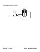
Page 85: ...f 8mA User IO Ground User IO Power 3V 35V 10 9 8 7 6 5 4 3 2 1 Camera IO Interface B E Common Ground Imax 8mA External Signal 0 Input 0 C External Input Using Common Emitter NPN Driver External Input maximum current is limited by the Calibir circuits to a maximum of 8mA User IO Ground 10 9 8 7 6 5 4 3 2 1 Camera IO Interface B E C Imax 8mA External Signal Common Ground Input 0 User IO Power 3V 35V...

Page 86: ...ical Specifications Calibir 640 GigE IR Camera User s Manual External Input Using a Balanced Driver RS 422 Compatible Transmitter 10 9 8 7 6 5 4 3 2 1 Camera IO Interface Common Ground Input 1 External Signal 0 ...

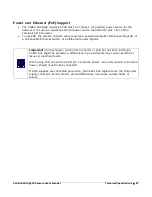
Page 87: ...puter NIC supporting PoE or a PoE capable Ethernet switch or an Ethernet power injector Important Connect power via the I O connector or PoE but not both Although Calibir 640 GigE has protection differences in ground levels may cause operational issues or electrical faults When using PoE the camera s I O pin 1 Camera Power Ground and pin 2 Camera Power Power must not be connected If both supplies ...

Page 88: ...88 Technical Specifications Calibir 640 GigE IR Camera User s Manual EC FCC Declarations of Conformity ...

Page 89: ...Calibir 640 GigE IR Camera User s Manual Technical Specifications 89 ...

Page 90: ...d 2 Option Discrete Cable Assembly www samtec com technical specifications Default aspx SeriesMaster SFSD Samtec ISDF 05 D ISDF 05 D M Discrete Connector www samtec com technical specifications Default aspx SeriesMaster ISDF ISDF 05 D M Connector Availability On Line North America specific country can be selected http www newark com samtec isd2 05 d m connector housing 10pos 2mm dp 84T0350 Europe ...

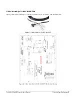
Page 91: ... Technical Specifications 91 Cable Assembly G3 AIOC BLUNT2M Open ended cable assembly to connect to Samtec 10 pin connector with thumbscrews Figure 45 Cable Assembly G3 AIOC BLUNT2M Figure 46 Cable Assembly G3 AIOC BLUNT2M Mechanical Drawing ...

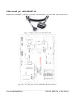
Page 92: ...Camera User s Manual Cable Assembly G3 AIOC BRKOUT2M Cable with terminal block breakout to connect to the Samtec 10 pin connector with thumbscrews Figure 47 Cable Assembly G3 AIOC BRKOUT2M Figure 48 Cable Assembly G3 AIOC BRKOUT2M Mechanical Drawing ...

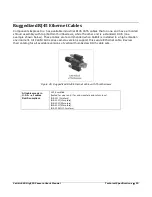
Page 93: ...se cables are recommended when Calibir is installed in a high vibration environment All Calibir 640 series camera versions support this secure Ethernet cable Review their catalog for all available versions of vertical thumbscrew RJ45 cable sets Figure 49 Ruggedized RJ45 Ethernet cable with Thumbscrews All cables made in U S A all cables RoHS compliant CAT6 certified tested for near end far end cro...

Page 94: ...e surface of the window barehanded will leave oily residues Using rubber finger cots and rubber gloves can prevent oil contamination However the friction between the rubber and the window may produce electrostatic charge that may damage the sensor Cleaning the Sensor Window Even with careful handling the sensor window may need cleaning The following steps describe various cleaning techniques to cl...

Page 95: ...s and network adapters which have caused problems with Calibir Emphasis is on the user to perform diagnostics with the tools provided and methods are described to correct the problem Quick Recovery Guide Typically the Sapera LT default configuration detects GenICam cameras automatically but it may be required to use the Network Configuration Tool distributed with Sapera LT as part of the Sapera Ne...

Page 96: ...rver Automatic IP DHCP Sapera Network Imaging Driver Enabled Included in the Discovery Process The camera should then be visible to the host computer s software When placing the mouse cursor over the GigE Vision Device Status in the system tray the number of available devices should be shown Double click the camera icon to show the GigE Vision Device Status window The Calibir camera should be list...

Page 97: ...D is off the power supply is not connected or faulty Verify the power supply voltage Camera is functional but image has no contents Aim the Calibir at an object with a temperature considerably higher lower from that of the ambient environment Using CamExert set the PixelFormat to 8 bits The camera should then generate well contrasted images Using CamExpert set the Calibir to output its Internal Pa...

Page 98: ...is indicates either a major camera fault or condition such as disconnected power or a network issue where there is no communication Refer to the Quick Start Guide and Camera Connection Setup sections to verify required installation steps Refer to the Teledyne DALSA Network Imaging manual to review networking details In multiple NIC systems where the NIC for the Calibir is using LLA mode ensure tha...

Page 99: ...o network issues may still not perform optimally Operational issues concerning cabling Ethernet switches multiple cameras and camera exposure are discussed in the following sections Always Important Power Failure During a Firmware Update Now What Cabling and Communication Problems See Preventing Operational Faults due to ESD to avoid random packet loss random camera resets and random loss of Ether...

Page 100: ...ll configuration parameters seem correct and the Ethernet cable is secure The following image shows an example of this type of bad acquisition while testing a Calibir installation with CamExpert Figure 50 Random Bad Data or Noise Example Some marginal NIC boards or ports can cause problems with packet transfers Try alternative NIC adapters Review other reasons for such acquisition errors as descri...

Page 101: ...estarted Cabling and Communication Problems Use a shielded cable where the connector shell electrically connects the Calibir chassis to the power supply earth ground Check that the Ethernet cable is clipped both to the Calibir and the NIC or switch on the other end Verify the Ethernet cabling Poor cables will cause connections to auto configure at lower speeds Use a secured Ethernet cable when the...

Page 102: ... were any problems with the automatic Calibir software installation Before Contacting Technical Support Carefully review the issues described in this Troubleshooting section To aid Teledyne DALSA personnel when support is required the following should be included with the request for support From the Start menu go to Programs Dalsa Sapera LT Tools and run the Log Viewer program From its File menu ...

Page 103: ...tion An object is present Orientation Object is symmetrical asymmetric horizontal or vertical Recognition The type of object can be discerned for example a person vs a vehicle Identification A specific object can be discerned for example a woman vs a man the specific vehicle Note These measurements give a 50 probability of an observer discriminating an object to the specified level However these m...

Page 104: ...104 Appendix Range Performance Calibir 640 GigE IR Camera User s Manual Theoretical Ranges for a 2 3 x 2 3m NATO Target Figure 52 Theoretical Ranges for a 2 3 x 2 3m NATO Target ...

Page 105: ...web site www teledynedalsa com corp contact Email mailto info teledynedalsa com Technical Support Submit any support question or request via our web site Technical support form via our web page Support requests for imaging product installations Support requests for imaging applications http www teledynedalsa com imaging support Camera support information Product literature and driver updates ...

Reviews: