20
|
Electrical installation
Installer and user reference guide
139
RYMA5+RXYA8~20A7Y1B
VRV 5 heat pump
4P749918-1 – 2023.12
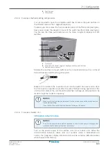
X2M
(SVS)
a
1
2
c
b
d
a
SVS output terminal
b
Relay
c
AC power supply 220~240 V AC
d
External alarm
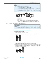
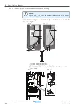
Cable routing
Route the SVEO or SVS output cable as indicated below.
5~12 HP
14~20 HP
a
b
b
b
b
a
Output cable (SVEO or SVS)(field supply)
b
Cable tie (accessory)
Alternate routing
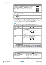
INFORMATION
Sound data about the refrigerant leakage alarm are available in the technical data
sheet of the user interface. E.g. the BRC1H52* controller generates an alarm of 65 dB
(sound pressure, measured at 1 m distance from the alarm).
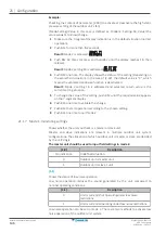
20.8 To check the insulation resistance of the compressor
NOTICE
If, after installation, refrigerant accumulates in the compressor, the insulation
resistance over the poles can drop, but if it is at least 1 MΩ, then the unit will not
break down.
▪
Use a 500 V mega-tester when measuring insulation.
▪
Do NOT use a mega-tester for low voltage circuits.
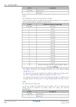
1
Measure the insulation resistance over the poles.
If
Then
≥1 MΩ
Insulation resistance is OK. This procedure is finished.
<1 MΩ
Insulation resistance is not OK. Go to the next step.
Summary of Contents for VRV 5 RXYA8A7Y1B
Page 197: ......
Page 198: ......
Page 199: ......
Page 200: ...4P749918 1 2023 12 Copyright 2023 Daikin Verantwortung f r Energie und Umwelt...


