21
|
Configuration
Installer and user reference guide
142
RYMA5+RXYA8~20A7Y1B
VRV 5 heat pump
4P749918-1 – 2023.12
Item
Description
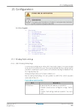
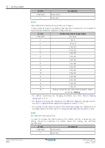
DIP switches
By operating the DIP switches it is possible to:
▪
DS1 (1): COOL/HEAT selector (refer to the manual of
the
cool/heat
selector
switch).
OFF=not
installed=factory setting
▪
DS1 (2~4): NOT USED. DO NOT CHANGE THE FACTORY
SETTING.
▪
DS2 (1~4): NOT USED. DO NOT CHANGE THE FACTORY
SETTING.
See also:
▪
"21.1.2 Field setting components"
▪
"21.1.3 To access the field setting components"
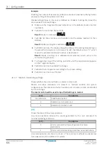
Mode 1 and 2
Mode
Description
Mode 1
(monitoring settings)
Mode 1 can be used to monitor the current situation of
the outdoor unit. Some field setting contents can be
monitored as well.
Mode 2
(field settings)
Mode 2 is used to change the field settings of the
system. Consulting the current field setting value and
changing the current field setting value is possible.
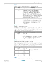
In general, normal operation can be resumed without
special intervention after changing field settings.
Some field settings are used for special operation (e.g.,
one time operation, recovery/vacuuming setting, manual
adding refrigerant setting, etc.). In such a case, it is
required to abort the special operation before normal
operation can restart. It will be indicated in below
explanations.
See also:
▪
"21.1.4 To access mode 1 or 2"
▪
▪
▪
"21.1.7 Mode 1: monitoring settings"
▪
"21.1.8 Mode 2: field settings"
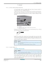
21.1.2 Field setting components
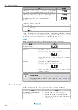
Location of the 7‑segment displays, buttons and DIP switches:
a
b
BS1 BS2
DS1 DS2
BS3
c
X27A
BS1
MODE: for changing the set mode
BS2
SET: for field setting
BS3
RETURN: for field setting
DS1, DS2
DIP switches
a
7-segment displays
Summary of Contents for VRV 5 RXYA8A7Y1B
Page 197: ......
Page 198: ......
Page 199: ......
Page 200: ...4P749918 1 2023 12 Copyright 2023 Daikin Verantwortung f r Energie und Umwelt...


