background image


SiK401004_A 

83 

INSTALLATION 

4.1.4 Connection of Signal Line of Wired Controller   

Caution:


Take great care when carrying out the following connections, so as to avoid 
malfunction of the air-conditioning unit because of electromagnetic interference.


 The signal line of the wire controller must be separated from the power line and the 

connecting line between the indoor unit and the outdoor unit. 

 In case the unit is installed in a place vulnerable by electromagnetic interference, it is 

better to use shielded cable or double-twisted cable as the signal line of the wired 
controller. 

 Open the cover of the electrical box of the indoor unit. 

 Pull the signal cable of the wired controller through the rubber bush. 

 Plug the signal line of the wired controller onto the 4-bit pin socket at the circuit board 

of the indoor unit. 

 Use cable fastener to bundle and fix the signal cable of the wired controller. 


4.1.5 Connection of Wiring 

  Disassemble right side panel and blow out hole for crossing wired on outdoor unit and 

cover it with cushion rubber.   

  Remove cable cleat, connect the connecting wire of power supply to the terminal and 

fix it. 

 Fix connecting wire of power supply and signal control wire with attached clamp 

without applying external pressure on the terminal parts, and then connect the 
corresponding connector. 

  Make sure that the wiring has been fixed. 

  Install the front side plate. 


Summary of Contents for RY24PEV1K

Page 1: ...SiK401004_A Duct type Applied Models Non Inverter Pair Cooling Only Non Inverter Pair Heat Pump...

Page 2: ...g 35 2 5 Fan Mode 36 3 WIRED REMOTE CONTROLLER 37 3 1 Displaying Part 38 3 2 Buttons 39 3 3 Installation of Wired Controller and Project Debugging 41 3 4 Instruction to Operation 43 3 5 Error Display...

Page 3: ...ion of Power Supply Wire and Air Switch 86 Part 4 MAINTENANCE 87 1 REMOTE CONTROLLER DISPLAY MALFUNCTION AND CONTENTS 88 2 FLOW CHART OF TROUBLESHOOTING 91 3 WIRING DIADRAM 101 3 1 Wiring Diagram Outd...

Page 4: ...plug socket before disassembling the equipment for a repair Working on the equipment that is connected to a power supply can cause an electrical shook If it is necessary to supply power to the equipme...

Page 5: ...ting cycle section is hot can cause burns Use the welder in a well ventilated place Using the welder in an enclosed room can cause oxygen deficiency 1 1 2 Cautions Regarding Products after Repair Warn...

Page 6: ...or pulling the power cable can damage the cable Do not mix air or gas other than the specified refrigerant R410A in the refrigerant system If air enters the refrigerating system an excessively high p...

Page 7: ...d if the connections at the soldered or crimped terminals are secure Improper installation and connections can cause excessive heat generation fire or an electrical shock If the installation platform...

Page 8: ...ution Caution A caution is used when there is danger that the reader through incorrect manipulation may damage equipment loose data get an unexpected result or has to restart part of a procedure Warni...

Page 9: ...PECIFICATIONS Part1 SPECIFICATIONS 1 MODELS LIST 2 1 1 Outdoor Unit 2 1 2 Indoor Unit 3 2 NOMENCLATURE 4 3 FUNCTION 5 4 PRODUCT DATA 6 4 1 Product Data at Rated Condition 6 4 2 Electrical Data 27 5 PI...

Page 10: ...r Unit Model Refrigerant Power Supply Appearance RY24PEV1K R24PEV1K R22 220 240V 1PH 50Hz RY30PEV1K R30PEV1K R22 220 240V 1PH 50Hz RY36PEY1K R36PEY1K R22 380 415V 3PH 50Hz RY42PEY1K R42PEY1K R22 380 4...

Page 11: ...26300 32100 FD Y M36PEV1K 33000 41000 FD Y M42PEV1K 38600 46100 Type FD Y M48PEV1K 44400 48200 R22 220 240V 1PH 50Hz Note 1Ton 12000Btu h 3 517kW Notes The universal outdoor units means that the cust...

Page 12: ...SiK401004_A SPECIFICATIONS 4 2 NOMENCLATURE 24 E K M V1...

Page 13: ...h low Pressure Protection when suction pressure is too low or discharge pressure is too high compressor will stop and unit displays malfunction code Overload protection compressor has its own overheat...

Page 14: ...Pa 25 EER Btu h W 9 28 Indoor Unit FDM24PEV1K Fan Motor Speed H M L r min 1250 1220 1060 Output of Fan Motor W 150 Fan Motor Capacitor F 8 Fan Type Piece Centrifugal fan 2 Diameter Length mm 160 200...

Page 15: ...r Unit 3200 Fan Type Piece Axial fan 1 Fan Diameter mm 450 Climate Type T3 Isolation I Moisture Protection IP24 Design Pressure Hi Lo MPa 2 5 0 6 Sound Pressure Level dB A 59 Sound Power Level dB H M...

Page 16: ...t FDM30PEV1K Fan Motor Speed H M L r min 1250 1220 1060 Output of Fan Motor W 150 Fan Motor Capacitor F 8 Fan Type Piece Centrifugal fan 2 Diameter Length mm 160 200 Evaporator Aluminum fin copper tub...

Page 17: ...or Unit 4200 Fan Type Piece Axial fan 1 Fan Diameter mm 552 Climate Type T3 Isolation I Moisture Protection IP24 Design Pressure Hi Lo MPa 2 5 0 6 Sound Pressure Level dB A 58 Sound Power Level dB H M...

Page 18: ...t FDM36PEV1K Fan Motor Speed H M L r min 1320 1090 910 Output of Fan Motor W 500 Fan Motor Capacitor F 12 Fan Type Piece Centrifugal fan 2 Diameter Length mm 200 190 Evaporator Aluminum fin copper tub...

Page 19: ...Unit 4000 Fan Type Piece Axial fan 1 Fan Diameter mm 482 Climate Type T3 Isolation I Moisture Protection IP24 Design Pressure Hi Lo MPa 2 5 0 6 Sound Pressure Level dB A 60 Sound Power Level dB H M L...

Page 20: ...it FDM42PEV1K Fan Motor Speed H M L r min 1320 1090 910 Output of Fan Motor W 500 Fan Motor Capacitor F 12 Fan Type Piece Centrifugal fan 2 Diameter Length mm 200 190 Evaporator Aluminum fin copper tu...

Page 21: ...6000 Fan Type Piece Axial fan 1 Fan Diameter mm 570 Climate Type T3 Isolation I Moisture Protection IP24 Design Pressure Hi Lo MPa 2 5 0 6 Sound Pressure Level dB A 60 Sound Power Level dB H M L A 70...

Page 22: ...Unit FDM48PEV1K Fan Motor Speed H M L r min 1320 1090 910 Output of Fan Motor W 500 Fan Motor Capacitor F 12 Fan Type Piece Centrifugal fan 2 Diameter Length mm 200 190 Evaporator Aluminum fin copper...

Page 23: ...6000 Fan Type Piece Axial fan 1 Fan Diameter mm 570 Climate Type T3 Isolation I Moisture Protection IP24 Design Pressure Hi Lo MPa 2 5 0 6 Sound Pressure Level dB A 60 Sound Power Level dB H M L A 70...

Page 24: ...h W 9 28 3 06 Indoor Unit FDYM24PEV1K Fan Motor Speed H M L r min 1250 1220 1060 Output of Fan Motor W 150 Fan Motor Capacitor F 8 Fan Type Piece Centrifugal fan 2 Diameter Length mm 160 200 Evaporato...

Page 25: ...3200 Fan Type Piece Axial fan 1 Fan Diameter mm 450 Defrosting Method Auto defrost Climate Type T3 Isolation I Moisture Protection IP24 Design Pressure Hi Lo MPa 2 5 0 6 Sound Pressure Level dB A 59...

Page 26: ...h W 8 92 2 85 Indoor Unit FDYM30PEV1K Fan Motor Speed H M L r min 1250 1220 1060 Output of Fan Motor W 150 Fan Motor Capacitor F 8 Fan Type Piece Centrifugal fan 2 Diameter Length mm 160 200 Evaporato...

Page 27: ...t 4200 Fan Type Piece Axial fan 1 Fan Diameter mm 552 Defrosting Method Auto defrost Climate Type T3 Isolation I Moisture Protection IP24 Design Pressure Hi Lo MPa 2 5 0 6 Sound Pressure Level dB A 58...

Page 28: ...W 8 46 3 48 Indoor Unit FDYM36PEV1K Fan Motor Speed H M L r min 1320 1090 910 Output of Fan Motor W 500 Fan Motor Capacitor F 12 Fan Type Piece Centrifugal fan 2 Diameter Length mm 200 190 Evaporator...

Page 29: ...000 Fan Type Piece Axial fan 1 Fan Diameter mm 482 Defrosting Method Auto defrost Climate Type T3 Isolation I Moisture Protection IP24 Design Pressure Hi Lo MPa 2 5 0 6 Sound Pressure Level dB A 61 So...

Page 30: ...W 8 04 3 25 Indoor Unit FDYM42PEV1K Fan Motor Speed H M L r min 1320 1090 910 Output of Fan Motor W 500 Fan Motor Capacitor F 12 Fan Type Piece Centrifugal fan 2 Diameter Length mm 200 190 Evaporator...

Page 31: ...Fan Type Piece Axial fan 1 Fan Diameter mm 570 Defrosting Method Auto defrost Climate Type T3 Isolation I Moisture Protection IP24 Design Pressure Hi Lo MPa 2 5 0 6 Sound Pressure Level dB A 61 Sound...

Page 32: ...h W 8 07 2 97 Indoor Unit FDYM48PEV1K Fan Motor Speed H M L r min 1320 1090 910 Output of Fan Motor W 500 Fan Motor Capacitor F 12 Fan Type Piece Centrifugal fan 2 Diameter Length mm 200 190 Evaporato...

Page 33: ...an Type Piece Axial fan 1 Fan Diameter mm 570 Defrosting Method Auto defrost Climate Type T3 Isolation I Moisture Protection IP24 Design Pressure Hi Lo MPa 2 5 0 6 Sound Pressure Level dB A 60 Sound P...

Page 34: ...6 F WB 19 C 66 2 F DB 35 C 95 F WB 24 C 75 2 F Heating DB 20 C 68 F WB C F DB 7 C 44 6 F WB 6 C 42 8 F Piping Length 5m The air volume is measured at the relevant standard external static pressure No...

Page 35: ...FLA Each FLA Each Amps Amps FD Y M24PEV1K R Y 24PEV1K 1 66 11 2 0 61 1 35 6 25 2 5 14 6 FD Y M30PEV1K R Y 30PEV1K 220 240V 1PH 50Hz 1 76 14 8 0 8 1 35 6 25 2 5 19 3 FD Y M36PEV1K R Y 36PEY1K 1 53 6 5...

Page 36: ...SiK401004_A SPECIFICATIONS 28 5 PIPING DIAGRAM...

Page 37: ...1 Cooling Mode 32 2 2 Dry Mode 33 2 3 Heating Mode 34 2 4 Defrosting 35 2 5 Fan Mode 36 3 WIRED REMOTE CONTROLLER 37 3 1 Displaying Part 37 3 2 Buttons 39 3 3 Installation of Wired Controller and Pro...

Page 38: ...for cooling dry operation is as follows Satisfying open Comp condition Temp of indoor Set temp Comp stop for 3 min N Y N Y Y N Unit start and running at cool or dry mode Indoor fan run Comp and outdoo...

Page 39: ...ion is as follows Satisfying open comp condition N Y N Y Y N Power On Comp and outdoor fan run Avoid cool wind only when comp start Temp of indoor Set temp Comp and outdoor fan stop Comp stop for 3 mi...

Page 40: ...s Tamb Tset 1 C Cooling mode will be entered In that case the compressor and outdoor unit fan runs and indoor unit fan runs at setting speed Tamb Tset 1 C Cooling OFF status will be entered In that ca...

Page 41: ...fan runs at low speed Tamb Tset 2 C Cooling OFF status will be entered In that case the compressor and outdoor unit fan stop running Tset 2 C Tamb Tset 2 C ON OFF alternated status will be entered In...

Page 42: ...indoor unit fan will run at setting speed and the mode of cold blast air prevention Tamb Tset 1 C The compressor and outdoor unit fan will stop but the 4 way valve will be still energized Indoor unit...

Page 43: ...continuous 1min defrosting starts If auxiliary heater is ON it will be stopped firstly At 10s later 4 way valve indoor and outdoor unit fans will be stopped while the compressor will compulsively run...

Page 44: ...ir supply mode Compressor Outdoor unit Fan Indoor unit Fan 4 way valve Manual ON Manual OFF OFF OFF OFF OFF OFF Running at setting speed H tap 5s Time The indoor unit fan will firstly run at high spee...

Page 45: ...SiK401004_A 37 FUNCTION CONTROL 3 WIRED REMOTE CONTROLLER 3 1 Displaying Part Fig 3 1 1 Outline of wired controller 3 1 1 LCD Display of Wired Controller Fig 3 1 2 LCD display...

Page 46: ...temperature on off mode or save is shielded by long distance monitoring 13 Turbo Turbo function state 14 Memory Memory state Indoor unit resumes original setting state after power failure and then pow...

Page 47: ...er blow quite 7 Timer Timer setting 8 On Off Turn on off indoor unit 4 Mode and 2 Memory function Press Mode and for 5s under off state of the unit to enter cancel key memory function If memory is set...

Page 48: ...continuously for 5s into debugging menu Press Mode button to adjust the setting items and or button to set the actual value 5 Function and 6 Enquiry of Historical Errors Continuously press Function a...

Page 49: ...t the back of controller s soleplate 3 Joint the controller s soleplate on wall face and then fix it in mounting hole with screws M4X25 4 Insert the 4 core twisted pair line through rectangle hole int...

Page 50: ...ed controller s address Press Function and Mode buttons at the same time for 5s In this case LCD displays address number Then press or button to adjust address address no 1 16 After that press Enter C...

Page 51: ...nit Note The state shown in Fig 3 4 1 indicates off state of the unit after energization The state shown in Fig 3 4 2 indicates on state of the unit after energization Fig 3 4 1 Off state of the unit...

Page 52: ...of them continuously temperature will be increased or decreased by 1 C every 0 5s In Cooling Dry Fan and Heating mode temperature setting range is 16 C 30 C In Auto mode the setting temperature is un...

Page 53: ...ing if Timer button is pressed LCD will display xx Hour ON blinking In this case press or button to adjust timer on and then press Timer to confirm If Mode button is pressed before pressing Timer butt...

Page 54: ...t is shown as Fig 3 4 6 Fig 3 4 6 Timer setting under on state of the unit Timer range 0 5 24hr Every press of or button will make setting time increased or decreased by 0 5hr If press either of them...

Page 55: ...s for 60min and fresh air valve runs for 2 4 min 5 The unit continuously runs for 60min and fresh air valve runs for 30 min 6 The unit continuously runs for 60min and fresh air valve runs for 36 min 7...

Page 56: ...wn as Fig 3 4 8 Fig 3 4 8 Sleep setting Sleep setting is clear after power failure and then power recovery There is not sleep function in fan and auto mode Note In cooling and dry mode if the unit wit...

Page 57: ...ayed 2 Turbo function will be automatically canceled after setting of quiet function 3 4 10 Save Function Setting Energy Saving Function Energy saving result that the air conditioner runs in smaller t...

Page 58: ...ction on the unit will be forcibly changed to corresponding mode After setting of save sleep function will be canceled 2 In save mode if Function button is pressed or there is not any operation within...

Page 59: ...on this function In this case E HEATER will be displayed which means E heater is allowed to be turned on If auxiliary electric heating function is on press Function button to confirm or press Enter Ca...

Page 60: ...o turn on this function In blow mode press Function button till the unit enters BLOW function and then press Enter Cancel button to cancel this function BLOW function setting is shown in Fig 3 4 12 Fi...

Page 61: ...function fan speed is un adjustable 2 When turning on auto quiet function the unit will enter quiet running state according to temperature difference between room temperature and setting temperature...

Page 62: ...lays 02 Three low grades indicate high medium and low grades and 3 high grades indicate super high high and medium grades Press Enter Cancel button to save the setting and quit after setting If there...

Page 63: ...r ambient sensor occurs this function will be shielded in 12hr 3 4 15 4 Enquiry of Historical Errors Continuously press Function and buttons without lock for 5s into enquiry state In this state press...

Page 64: ...ind Pipe series have multiple units Multi system is only for air cooled packaged unit Malfunction code list Fig 3 5 1 Malfunction code list Malfunction code Description E1 Actuation of high pressure s...

Page 65: ...inside the wired controller User can select one from the two indoor room sensors on the basis of the engineering requirement Refer to the section of wire controller instructions for detailed operatio...

Page 66: ...tates the health of users but also controls the electricity consumption loss due to take fresh air in This kind of control can be carried out through the wired controller The function can set at any t...

Page 67: ...ace mounted use 1 metallic pipe and make matching recess in the wall refer to Figure 3 6 4 If concealed installation is adopted 1 metallic pipe can be used Refer to Figure 3 6 5 No matter if surface m...

Page 68: ...Site 69 2 3 Cautions for Installation 70 2 4 Dimension Data 71 2 5 Installation Clearance Data 72 3 REFRIGERATION PIPING WORK 73 3 1 Refrigeration Piping Work Procedures 73 3 2 Caution in Connecting...

Page 69: ...far away from where the flammable or explosive substances are stored to avoid explosion or fire may occurred by leakage of such substances 1 1 2 Installation Site Ensure the top hanging piece has str...

Page 70: ...Supply Air Intake Nut Hanger Screw mm I Enlargement I Figure 1 1 5 6 Precautions for unfavorable installation The preparation of all pipes connecting pipes and drainage pipes and cables connecting lin...

Page 71: ...the unit which is shown as below Air Supply Air Intake i Condensate Drainpipe Level Instrument Condensate Drainpipe Enlarged View As the inside of the unit is in the negative pressure status it is re...

Page 72: ...iquid joint of the indoor unit Heat Insulator of drain Pipe 2 for wrapping condensate pipe and rubber plug Nut with Washer M8 8 for fixing hook hitch Nut with Washer M10 4 Nut and Spring Pad 4 4 sets...

Page 73: ...drainage pipe with the unit do not apply excessive force to the pipeline at the side of the unit The bunging position of the pipeline shall be near the unit Purchase general purpose hard PVC pipe loc...

Page 74: ...pipe and the fresh air pipe must be covered with a layer of thermal insulation so as to avoid thermal leakage and condensation Firstly apply liquid nail on the ducts then attach the thermal insulatio...

Page 75: ...er 5 Air Inlet 2 Air Intake Duct 6 Main Air Supply Duct 3 Canvas Air Duct 7 Air Outlet 4 Air Inlet Installation of Round Air Duct as shown in Figure 1 1 12 Figure 1 1 12 S N Name S N Name 1 Hanger 6 T...

Page 76: ...pes Indoor unit InstallBottom Sketch for installing 3 round outlet pipes Round outlet pipe Hole Round outlet pipe parts Outlet pipe parts Enclosure Tighten the parts by bolts as shown in the figure If...

Page 77: ...tion must be in accordance with following principles Outdoor unit shall be installed so that the air discharged by outdoor unit will not return and that sufficient space for repair shall be provided a...

Page 78: ...uts and make sure the verticality and horizontality of the unit Lift the outdoor unit with indicated holes for hoist Protect the unit from corrosion when lifting in case it will rust Rubber vibration...

Page 79: ...2 4 Dimension Data Figure 2 4 1 Unit mm Model A B C D E RY24PEV1K 1018 412 695 572 378 RY30PEV1K R30PEV1K 980 427 790 610 395 RY36PEY1K RY36PEY1K 1018 412 840 572 378 RY42PEY1K R42PEY1K RY48PEY1K RY48...

Page 80: ...SiK401004_A INSTALLATION 72 2 5 Installation Clearance Data Figure 2 5 1...

Page 81: ...SiK401004_A 73 INSTALLATION 3 REFRIGERATION PIPING WORK 3 1 Refrigeration Piping Work Procedures 1 Connecting Pipe Figure 3 1 1...

Page 82: ...que needed for tightening nut Diameter of Pipe Tightening torque 1 4 15 30 N m 3 8 35 40 N m 5 8 60 65 N m 1 2 45 50 N m 3 4 70 75 N m Degree of curvature of the tubing cannot be too small or the pipe...

Page 83: ...valve and screw the bonnet tightly Open stem of gas valve and liquid valve completely as figure 3 1 4 Figure 3 1 4 Screw the bonnet tightly and then detect if there is any leakage on the joint connect...

Page 84: ...the valve stem of the gas valve as well as the liquid valve entirely Tighten the valve stem of the gas valve and liquid valve so as to check whether leakage occurred 3 Installation of Protective Layer...

Page 85: ...pe the later circle of tape must cover half of the front circle of tape Figure 3 1 7 Wrapped pipe must be fixed to wall using pipe clamps Caution After the pipes are wrapped by protective materials ne...

Page 86: ...k if the lubricant of the system is enough If not add some oil trap properly Refrigerants volume inside the outdoor unit suit for connecting pipe with 7m If connecting pipe shall be prolonged refriger...

Page 87: ...um Length of Connection Pipe Maximum Difference in Height between Outdoor and Indoor Unit Additional Charge of Refrigerant Model Gas Pipe Liquid Pipe m m g m RY24PEV1K R24PEV1K RY30PEV1K R30PEV1K 5 8...

Page 88: ...nal be suffered from force And do not drag the power cable forcibly The wire diameter of power cable should be large enough If power cable and connection wire be damaged it should be replaced by the e...

Page 89: ...lled in the fixed line 2 Connection of single wire Use wire stripper to strip the insulation layer 25mm long from the end of the single wire Remove the screw at the terminal board of the air condition...

Page 90: ...unit Do not let any cable contact the refrigerant pipe the compressor and moving parts such as fan Do not change the internal line connections inside the air conditioning unit The manufacturer shall...

Page 91: ...ver of the electrical box of the indoor unit Pull the signal cable of the wired controller through the rubber bush Plug the signal line of the wired controller onto the 4 bit pin socket at the circuit...

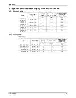
Page 92: ...04_A INSTALLATION 84 4 2 Electric Wiring Design RY24PEV1K R24PEV1K FD Y M24PEV1K RY30PEV1K R30PEV1K FD Y M30PEV1K Power cord 3x4 mm2 H07RN F Power cord 3x1 0 mm2 H05VV F Communication cords 2 0 75mm2...

Page 93: ...INSTALLATION RY36PEY1K R36PEY1K FD Y M36PEV1K RY42PEY1K R42PEY1K FD Y M42PEV1K RY48PEY1K R48PEY1K FD Y M48PEV1K Power cord 5x4mm2 H07RN F Power cord 3x1 5 mm2 H05VV F Communication cords 2 0 75mm2 H0...

Page 94: ...0 240 1 50 25 4 0 4 0 RY36PEY1K R36PEY1K 380 415 3 50 20 4 0 4 0 RY42PEY1K R42PEY1K 380 415 3 50 25 4 0 4 0 RY48PEY1K R48PEY1K 380 415 3 50 25 4 0 4 0 4 3 2 Indoor Unit Duct Type Capacity of breaker M...

Page 95: ...R DISPLAY MALFUNCTION AND CONTENTS 88 2 FLOW CHART OF TROUBLESHOOTING 91 3 WIRING DIADRAM 101 3 1 Wiring Diagram Outdoor Units 101 3 2 Wiring Diagram Indoor units 109 4 DISASSEMBLY AND ASSEMBLY PROCED...

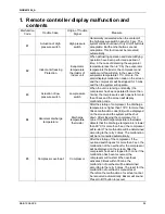
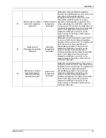
Page 96: ...han 3mins the low pressure switch opens for more than 30sec and the screen will display malfunction code E4 Abnormal discharge temperature Discharge temperature thermistor After the startup of compres...

Page 97: ...rmistor will be reset in air supply mode the malfunction code F0 will disappear on the screen and the indoor unit fan will run normally F1 Malfunction of evaporator temperature thermistor Evaporator t...

Page 98: ...rge temperature thermistor for more than 5 sec The system will be shut down in cooling operation and dehumidifying operation The screen will display the malfunction code F4 on the screen The reset for...

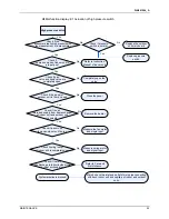
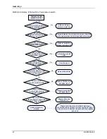
Page 99: ...he status of the complete device and do not observe the partial device It is advised to start from the simple operation during analyzing judging and confirming malfunction reason then conduct the comp...

Page 100: ...r unit and outdoor unit is smooth Check if the panel of outdoor unit is firmly closed Check if gas valve and liquid valve are completely open Check if operation mode of indoor unit is properly set Che...

Page 101: ...input Refer to Care and Maintenance Mainly check the inlet and outlet of main pipe connecting with each indoor unit and capillary of indoor and outdoor units Replace the parts like filter capillary a...

Page 102: ...ischarge temperature sensor No Measure if compressor s discharge temperature has reached 130 C System pipeline leaks so complementation is needed Please add refrigerant according to the amount specifi...

Page 103: ...s connection line No Replace main board Replace overheat protector Refer to E1 Contact the power supplier Check if compressor s connection line is properly connected Check if current value is higher...

Page 104: ...e locations of plug and socket No Equip the ferrite cores No Energize the outdoor unit Replace the controller Check if communication line is closed circuit Check if the communication line between indo...

Page 105: ...water drainage pipe Check the liquid level switch Replace the main board of the indoor unit Check the cables of water drainage pump Check if water overflow Check if the water drainage pump works Chec...

Page 106: ...nsor is correctly connected with socket on the mainboard Replace mainboard of the indoor unit Replace temperature sensor No Yes Yes Remove the sensor to check if the resistance value is ok Yes Check t...

Page 107: ...rrectly connected with socket on the mainboard Replace mainboard of the indoor unit Replace temperature sensor No Yes Yes Remove the sensor to check if the resistance value is ok Yes Check the directi...

Page 108: ...1004_A MAINTENANCE 100 Malfunction display F5 Malfunction of Indoor Room Thermistor at Wired Controller Malfunction of indoor room thermistor at wired controller Replace Wired Controller of the indoor...

Page 109: ...SiK401004_A 101 MAINTENANCE 3 WIRING DIADRAM 3 1 Wiring Diagram Outdoor Units 3 1 1 RY24PEV1K 6 3 6 2 5 3 6 5...

Page 110: ...SiK401004_A MAINTENANCE 102 3 1 2 R24PEV1K 6 3 6 2 5 6 4 3...

Page 111: ...SiK401004_A 103 MAINTENANCE 3 1 3 RY30PEV1K 6 3 6 2 5 3 6 6...

Page 112: ...SiK401004_A MAINTENANCE 104 3 1 4 R30PEV1K 6 3 6 2 5 6 5 0...

Page 113: ...SiK401004_A 105 MAINTENANCE 3 1 5 RY36PEY1K...

Page 114: ...SiK401004_A MAINTENANCE 106 3 1 6 R36PEY1K L L...

Page 115: ...SiK401004_A 107 MAINTENANCE 3 1 7 RY42PEY1K RY48PEY1K L L...

Page 116: ...SiK401004_A MAINTENANCE 108 3 1 8 R42PEY1K R48PEY1K L L...

Page 117: ...SiK401004_A 109 MAINTENANCE 3 2 Wiring Diagram Indoor units 3 2 1 Duct Type Model FD Y M24PEV1K FD Y M30PEV1K FD Y M36PEV1K FD Y M42PEV1K FD Y M48PEV1K...

Page 118: ...crew on the rear grill with screwdriver Remove rear grill from the unit 3 Disassembly of front grill Disassemble the screws of the front grill with screwdriver Disassemble and remove the front grill f...

Page 119: ...0PEV1K R Y 36PEV1K R Y 42PEV1K R Y 48TPEV1K need to be equipped with front panel outside the external casing 8 Installation of front grill Put new front grill into correct position on the unit Screw d...

Page 120: ...ts on compressor Disassemble the retaining nuts on the compressor with wrench 3 Dismantle the discharge pipe and the suction pipe of compressor Heat the suction and discharge pipe with gas welding bef...

Page 121: ...wn the retaining screw for the power supply wires with screwdriver 8 Vacuumization by fluorin feeding nozzle Vacuumize the system by fluorin feeding nozzle 9 Recharge refrigerants by fluorin feeding n...

Page 122: ...ay valve 4 Removal of 4 way valve Remove the old 4 way valve from the pipe line 5 Installation of New 4 way valve Position accurately the new 4 way valve Connect new 4 way valve with pipe line Wrap th...

Page 123: ...connected with other pipe lines Re conduct the system leak test Pump vacuum and fill the refrigerants Disassembly and Assembly of Vapour Liquid Separator Remark Make sure that there isn t any refrige...

Page 124: ...n above in order to disassemble axial flow fan and motor conveniently 2 Disassembly of axial flow fan Hold the fans without movement Disassemle retaining nuts for the fans with wrench Take down and re...

Page 125: ...power supply of the unit is cut down before removal of electrical parts box or electrical parts box modules Step Illustration Handling Instruction 1 Disaasembly of cover of electrical box Cut off pow...

Page 126: ...tition Remove sub assy of electric box 5 Install new sub assy of electric box Position accurately the new sub assy of electrical box Re fasten the sub assy of electrical box and screw down with screwd...

Page 127: ...r supply is cut off before disassembling and protect all the parts during disassembly Do not put filter screen near the high temperature heat source Step Illustration Handling Instruction Disassembly...

Page 128: ...t dampen or hit them Step Illustration Handling Instruction 1 Disassembly of electric box cover Remove the screw according to the position shown in the circle and the box and remove the electrical box...

Page 129: ...crews on seal plates of indoor panels and the pump drainage pipe Remove the seal plates As is shown in the illustration the circle represents screws on seal plates and box the screws on drainage pipe...

Page 130: ...the fastening screws on the cover plate and remove the cover plate As is shown in the illustration circle represents 6 screws under the cover plate and the box represents two screws on water containin...

Page 131: ...protect all the parts during disassembly Step Illustration Handling Instruction 1 Disassembly of fan Remove the fixing screws on the fan components As shown in the illustration circle represents 6 scr...

Page 132: ...screw connecting left and right side panels on the evaporator and the upper cover plate As shown in the arrow s direction in the illustration 2 Disassembly of the screws connecting evaporator valve s...

Page 133: ...isassembly Step Illustration Handling Instruction 1 Disassembly of the screws on the cover plates Remove the screws between right and left panels and upper cover plates Remove right and left panels As...

Page 134: ...mporter distributor and or retailer Cautions on product corrosion 1 Air conditioners should not be installed in areas where corrosive gases such as acid gas or alkaline gas are produced 2 If the outdo...

Reviews: