background image

English

7

4.

Knockout hole

5.

Side of unit

6.

Front of unit

7.

Terminal block

8.

Control Box

<Precautions when laying power wiring>

• Wiring of different thicknesses cannot be connected to the power ter-

minal block. 
(Slack in the power wiring may cause abnormal heat.)

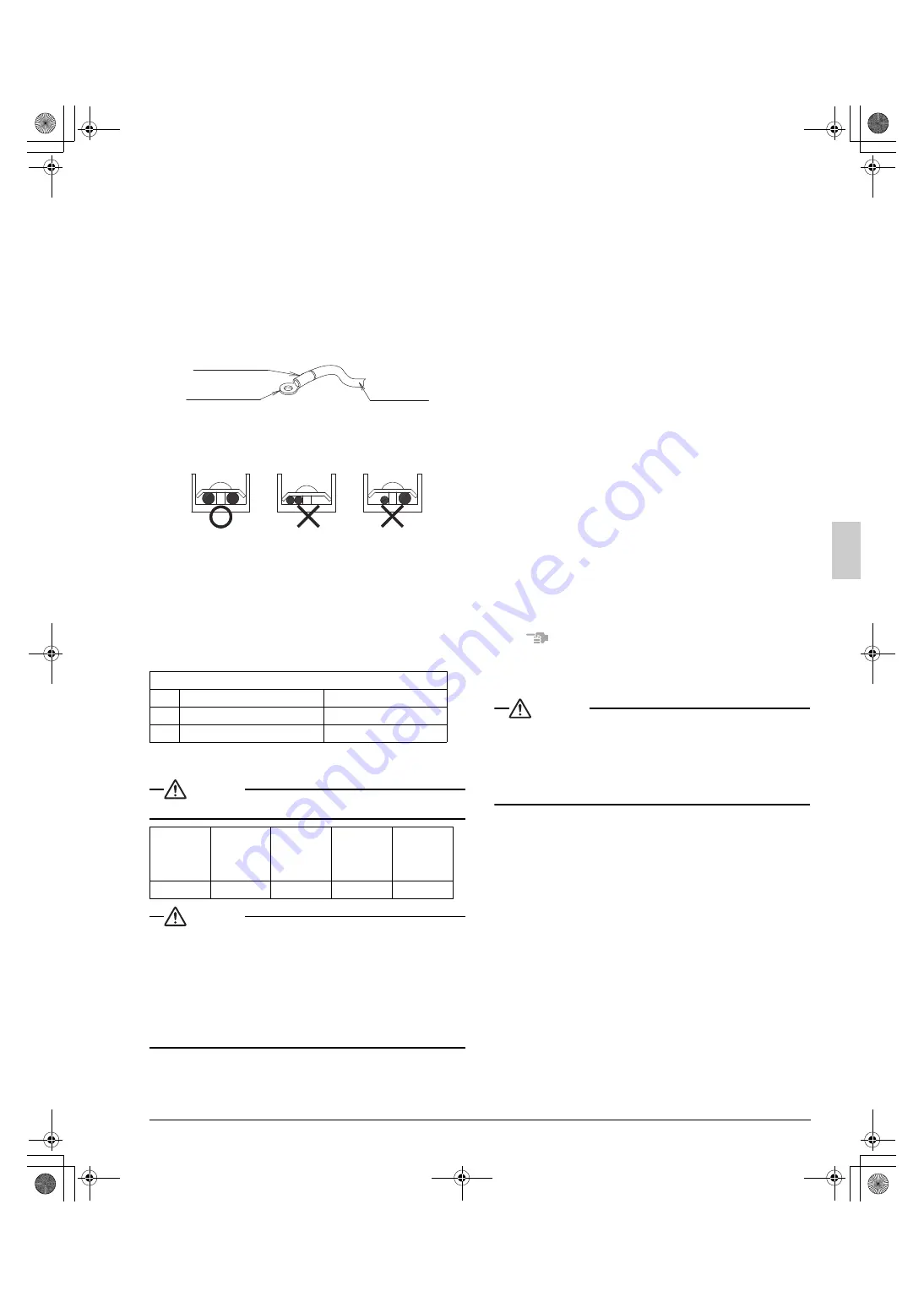
• Use sleeve-insulated round pressure terminals for connections to 

the power terminal block. When none are available, connect wire of 
the same diameter to both sides, as shown in the figure.

Follow the instructions below if the wiring gets very hot due to 
slack in the power wiring.

• For wiring, use the designated power wire and connect firmly, then 

secure using the included clamping material to prevent outside pres-
sure being exerted on the terminal board.

• Use an appropriate screwdriver for tightening the terminal screws.

A screwdriver with a small head will strip the head and make proper 
tightening impossible.

• Over-tightening the terminal screw may break it.

See the table below the tightening torque of the terminal screws.

6-3 How to connect the power supply wiring

CAUTION

Attach a circuit breaker/GFCI.

CAUTION

• The wiring should be selected in compliance with local specifica-

tions. See the table above.

• Always turn off the power before doing wiring work.
• Grounding should be done in compliance with local laws and reg-

ulations.

• As shown in figure 18, when connecting the power supply wiring to 

the power supply terminal block, be sure to clamp securely.

• Once wiring work is completed, check to make sure there are no 

loose connections among the electrical parts in the control box.

(Refer to figure 17)

1.

Stop valve attachment plate

2.

Clamp (accessory)

3.

Connecting power supply wiring

4.

Ground wire (Yellow/Green)

5.

Terminal block (X1M)

6.

Transmission wiring

7.

(To X2M [TO IN/ D UNIT] (F1, F2))

8.

Terminal block (X2M)

9.

Insulation tube (Large) (accessory)

10.

Insulation tube (Small) (accessory)

11.

Cut off the insulation tube sticking out of the outdoor unit.

6-4 Transmission wiring connection procedure

• Between indoor units in the same system, pass the wiring between 

the units as shown in figure 18. (There is no polarity.)

(Refer to figure 18)

1.

Terminal block (X2M)

2.

Use balance type shield wire (with no polarity).

3.

Indoor unit

4.

Under no circumstances should 208/230V be connected.

Precautions regarding the length of wiring between units

Exceeding the following limits may cause transmission malfunctions, so 
observe them.
Max. wiring length

Max. 984ft.(300m)

Total wiring length

Max. 1968ft.(600m)

Max. no. of branches 8

Precautions regarding wiring between units

Do not connect 208/230V power wiring to terminals for the 
transmission wiring. Doing so would destroy the entire system.

• Wiring to the indoor unit should be wired to F1 and F2 (TO IN/D unit) 

on the outdoor unit’s terminal block (X2M).

NOTE

The above wiring should be wired using AWG18-16 stranded, non-
shielded wiring. 
(See figure 18 for how to ground the shielded parts.)

All transmission wiring is to be procured on site.

CAUTION

Up to 8 branches are available in the wiring among units.

Branch after branch cannot perform wiring between units.

(Refer to figure 19)

1.

Branch

2.

Branches after branch points

3.

Caution on branches in the wiring among units

7.

PRECAUTIONS ON REFRIGERANT PIPING

• Do not allow anything other than the designated refrigerant to get 

mixed into the refrigerant cycle, such as air, nitrogen, etc. If any 
refrigerant gas leaks while working on the unit, ventilate the room  
thoroughly right away.

• Use R410A only when adding refrigerant.
• Installation tools:

Make sure to use installation tools (gauge manifold, charge hose, 
etc.) that are exclusively used for R410A installations to withstand 
the pressure and to prevent foreign materials (e.g., mineral oils and 
moisture) from mixing into the system.

• Vacuum pump:

• Use a 2-stage vacuum pump with a non-return valve.
• Make sure the pump oil does not flow oppositely into the system 

while the pump is not working.

• Use a vacuum pump which can evacuate to 500 microns.

Tightening torque (ft·lbf / N·m)

M5

Power terminal

1.76~2.15 / 2.39~2.91

M4

Shield ground

0.87~1.06 / 1.18~1.44

M3

Transmission wiring terminal block

0.58~0.72 / 0.8~0.97

Model name

Phase and 

frequency

Voltage

Maximum 

overcurrent 

protective 

device

Minimum 

circuit 

ampacity

RXSQ60 type

1~60Hz

208/230V

35A

29.1A

Insulating sleeve 

Round crimp-style 
terminal

Electric Wire

Connect wires 
of the same gauge 
to both side.

Do not connect 
wires of different 
gauges.

Do not connect 
wires of the same 
gauge to one side.

01_EN_3P591321-3B.fm  Page 7  Tuesday, December 24, 2019  10:28 AM

Summary of Contents for RXSQ60TAVJUA

Page 1: ...nual Residential VRV System air conditioner Manuel d installation Climatiseur syst me VRV r sidentiel Espa ol Manual de instalaci n Acondicionador residencial de aire sistema VRV Residential VRV INSTA...

Page 2: ...s inch mm 40 1000 or more 40 1000 or more 20 500 or less 12 300 or more 8 200 or more 4 100 or more 4 100 or more figure 5 figure 6 1 2 3 4 20 500 or more 20 500 or less 20 500 or more 40 1000 or more...

Page 3: ...4 100 or more inch mm 4 100 or more 4 100 or more 4 100 or more 4 100 or more 4 100 or more 4 100 or more L H A 60 1500 or more 24 600 or more 120 3000 or more 1 13 16 20 inch mm 1 2 7 3 4 6 5 figure...

Page 4: ...1 2 3 4 4 5 6 1 2 3 5 6 8 4 7 1 2 3 4 4 1 3 2 figure 21 figure 22 figure 23 figure 24 1 2 3 4 5 1 2 1 2 3 4 5 6 7 11 8 9 10 figure 25 figure 26 figure 27 1 2 3 4 5 6 7 8 figure 28 figure 29 Maximum a...

Page 5: ...lt in serious injury or death Do not ground units to water pipes gas pipes telephone wires or lightning rods as incomplete grounding will result a severe shock hazard resulting in severe injury or dea...

Page 6: ...scent lamps as much as possible Indoor units are for indoor installation only Outdoor units can be installed either outdoors or indoors This unit is for outdoor use Do not install the air conditioner...

Page 7: ...y accessories and parts which are of the designated specifica tion when installing 4 SELECTING INSTALLATION SITE 1 Select an installation site where the following conditions are satisfied and that mee...

Page 8: ...ance lev els especially in small rooms so steps need to be taken to prevent refrigerant leakage See the equipment design reference for details 6 Inverter type air conditioners sometimes cause static i...

Page 9: ...MULTIPLE ROW INSTALLATION FOR ROOF TOP USE ETC 1 In case of installing one unit per row Refer to figure 10 1 2 In case of installing multiple units 2 units or more in lateral connec tion per row Refe...

Page 10: ...n a wiring pipe or plastic tube to protect it Secure the wiring with the included clamp so that it does not come in contact with the piping or stop valve See 6 3 How to connect the power supply wiring...

Page 11: ...with no polarity 3 Indoor unit 4 Under no circumstances should 208 230V be connected Precautions regarding the length of wiring between units Exceeding the following limits may cause transmission malf...

Page 12: ...performing nitrogen replacement or releasing nitro gen into the piping will create large quantities of oxidized film on the inside of the pipes adversely affecting valves and compressors in the refrig...

Page 13: ...insulation material on liquid pipe when it has the possibility of getting in contact with the terminal Also make sure that the interunit piping does not touch the mounting bolt of the compressor Refe...

Page 14: ...0 5m Pipe length from rst refrigerant branch kit either refnet joint or refnet header to indoor unit 100ft 30 5m Example unit 8 i 100ft 30 5m Example unit 6 b h 131ft 40m unit 8 i k 100ft 30 5m Refrig...

Page 15: ...94 Put connected indoor unit Qty based on table below 2 49 Indoor type table 3 44 A coil 3 75 FXMQ FXEQ FXUQ FXFQ FXZQ FXHQ FXLQ FXDQ FXTQ FXAQ CXTQ 4 78 A Total G2 G3 24 36 G4 B 2 40 G5 G6 A B G7 A B...

Page 16: ...p valve Close 10 Indicates local procurement 11 Outdoor unit NOTE The stop valve must always be turned to closed Otherwise the refrigerant in the outdoor unit will pour out The names of parts needed t...

Page 17: ...All indoor units connected to the outdoor unit operate automatically Complete work on the indoor units in order to ensure maximum safety 10 1 Power On Check Operation Make sure to perform the check o...

Page 18: ...see if cold or hot air is coming out of the indoor unit 4 Press the fan direction and fan strength buttons on the indoor unit to see if they operate properly Precautions during temperature control ch...

Page 19: ...refrigerant temperature to match the required load which is also related to the outdoor ambient conditions E g when your system is operating in cooling you do not need as much cooling under low outdoo...

Page 20: ...ing on the situation When the request from the indoor units becomes more moderate the system will eventually go to the steady state condition which is defined by the operation method above To activate...

Page 21: ...Type Description Actions Field setting Shorted between Heating Thermo on Heating Thermo off Heater Fan Heater Fan I Heat pump heating is always locked out 2 16 ON ON ON H L OFF LL II Mode 1 Lockout i...

Page 22: ...ilure related to outdoor units No Setting item display Setting condition display Setting item MODE H1P TEST H2P C H selection Low noise H6P Demand H7P IND H3P Master H4P Slave H5P Factory setting 57 H...

Page 23: ...damage due to sweating and cause compressor damage and void warranty Standard pipe connection Gas side Standard diameter Existing pipe connection Gas side Larger pipe Liquid side No inslated Existing...

Page 24: ...unit set temperature B Operation start C Operating time D Mild E Quick F Powerful Example Automatic mode during heating A B 100 70 E Tc C D 120 F 49 C F 115 F 46 C 36 F 2 C A Virtual load curve defau...

Page 25: ...action is necessary to comply 1 Calculate the amount of refrigerant lb charged to each system separately NOTE Where a single refrigerant facility is divided into 2 entirely indepen dent refrigerant sy...

Page 26: ...Daikin Texas Technology Park 19001 Kermier Road Waller TX 77484 U S A 2001 3P591321 3B EM19A006A HT 00_CV_3P591321 3B fm Page 5 Friday December 20 2019 4 17 PM...

Reviews: