


English
11
•
When two wires are connected to a single terminal, connect them so
that the rear sides of the crimp contacts face each other. Also, make
sure the thinner wire is on top, securing the two wires simultaneously
to the resin hook using the included clamp (1).
7-6 Procedure for Wiring Inside Units
•
Referring to figure 23, secure and wire the power and transmission
wiring using the included clamp (1), (2), and (3).
•
Wire so that the ground wiring does not come into contact with the
compressor lead wiring.
If they touch, this may have an adverse effect on other devices.
•
The transmission wiring must be at least 2 in. away from the power wiring.
•
Make sure all wiring do not contact to the pipes (hatching parts in the
figure 23).
(Refer to figure 23)
1.
Secure to the hook of column support using the accessory
calmp (1).
2.
Electric conduit
3.
When routing out the power/ground wires from the left side.
4.
When routing out the transmission wiring from the opening
for piping.
5.
When routing out the power/ground wires from the front.
6.
Clear over 2 in..
7.
When routing out the transmission wiring from the knockout
hole.
8.
When routing out the power/ground wires from the right side.
9.
Power wiring
10.
Ground wire
11.
Transmission wiring
12.
When wiring, exercise sufficient caution not to detach the
acoustic insulators from the compressor.
13.
Secure to the back side of the support beam using the
accessory clamp (1).
14.
Retain to the back of the column support with the accessory
clamp (2).
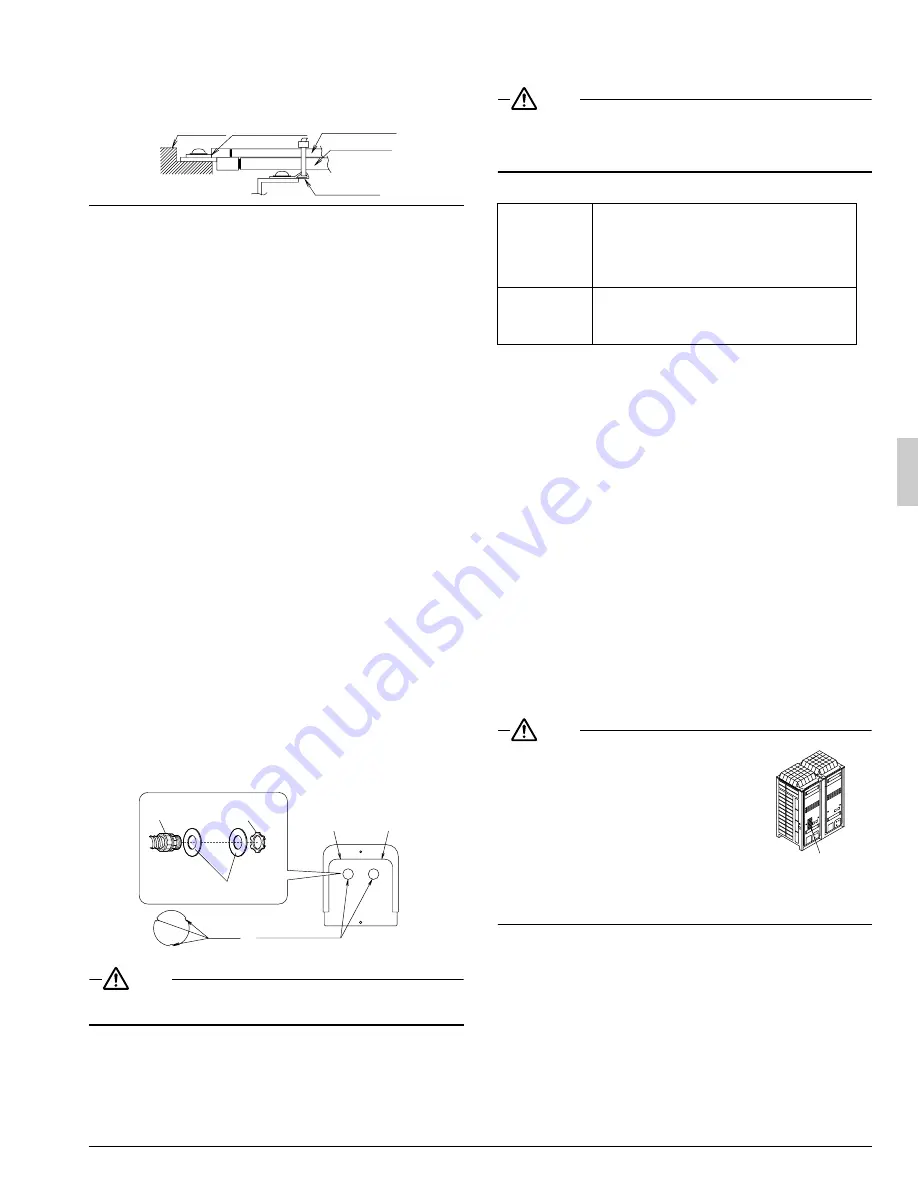
Precautions when knocking out knockout holes
•
To punch out a knockout hole, hit it with a hammer.
•
Open an appropriate hole as needed.
•
After knocking out the holes trim off the burr, then we recommend
you to paint the edges and areas around the edges using the repair
paint to prevent rusting.
•
Power line : Open a knockout hole as shown at left and connect
it using a conduit.
•
Transmission line : Connect it using a conduit in the knockout hole
on the right.
NOTE
•
After wiring work is completed, check to make sure there are no loose
connections among the electrical parts in the EL.COMPO.BOX.
8.
AIR TIGHT TEST AND VACUUM DRYING
•
After finished piping work, carry out air tight test and vacuum drying.
NOTE
•
Always use nitrogen gas for the airtightness test.
•
Absolutely do not open the shutoff valve until the main power ciruit
insulation measurement has been completed. (measuring after the
shutoff valve is opened will cause the insulation value to drop.)
<Needed tools>
<The system for air tight test and vacuum drying>
•
Referring to figure 24, connect a nitrogen tank, refrigerant tank, and
a vacuum pump to the outside unit.
The refrigerant tank and the charge hose connection to refrigerant
charge port or the valve A in figure 24 are needed in
“11. ADDI-
TIONAL REFRIGERANT CHARGE AND CHECK OPERATION”
.
(Refer to figure 24)
1.
Gauge manifold
2.
Nitrogen
3.
Measuring device
4.
R410A tank (with siphon)
5.
Vacuum pump
6.
Charge hose
7.
Refrigerant charge port
8.
HP/LP gas pipe shutoff valve
9.
Suction gas pipe shutoff valve
10.
Liquid pipe shutoff valve
11.
Valve A
12.
Valve B
13.
Valve C
14.
Outside unit
15.
To BS (or indoor) unit
16.
Shutoff valve
17.
Service port
18.
Field piping
19.
Gas flow
NOTE
•
The air-tightness test and vacuum drying
should be done using the service ports of
equalizer pipe, HP/LP gas pipe, suction gas
pipe and liquid pipe shutoff valve.
See the [R410A] Label attached to the front
plate of the outside unit for details on the loca-
tion of the service port (see figure at right)
•
See
[Shutoff valve operation procedure]
in
“11-1 Before working”
for details on handling
the shutoff valve.
•
The refrigerant charge port is connected to unit pipe.
When shipped, the unit contains the refrigerant, so use caution when
attaching the charge hose.
<Air tight test>
Pressurize the liquid pipe, suction gas pipe, HP/LP gas pipe and
equalizer pipe from the service ports of each shutoff valve to 550 psi
(do not pressurize more than 550 psi). If the pressure does not drop
within 24 hours, the system passes the test.
If there is a pressure drop, check for leaks, make repairs and perform
the airtight test again.
Terminal
block
Crip style
terminal
Wire : narrow
Wire : thick
Resin hook
Burr
Knockout hole
Left side
Right side
Conduit
(field supply)
Lock nut
(field supply)
Conduit mounting plate
(accessory)
Gauge manifold
Charge hose
valve
•
To prevent entry of any impurities and insure
sufficient pressure resistance, always use the
special tools dedicated for R410A.
•
Use charge hose that have pushing stick for
connecting to service port of shutoff valves or
refrigerant charge port.
Vacuum pump
•
The vacuum pump for vacuum drying should
be able to lower the pressure to –14.6 psi.
•
Take care the pump oil never flow backward
into the refrigerant pipe during the pump stops.
[R410A] Label


