


30
5.2 Setting Group Address for Centralized Control
Fundamental of DIII-NET
ED721208
5.2
Setting Group Address for Centralized Control
Set the group address of each group of the indoor unit from the remote controller. (In case of no remote controller, also
connect the remote controller and set the group address. Then, remove the remote controller.)
* Group address can not be set without centralized control equipment.
Cautions:
When the power is supplied, all the display appears once on the remote controller and then the display changes to [88] for
about one minute and during that time the remote controller does not function. However, this is not a malfunction of
remote controller.
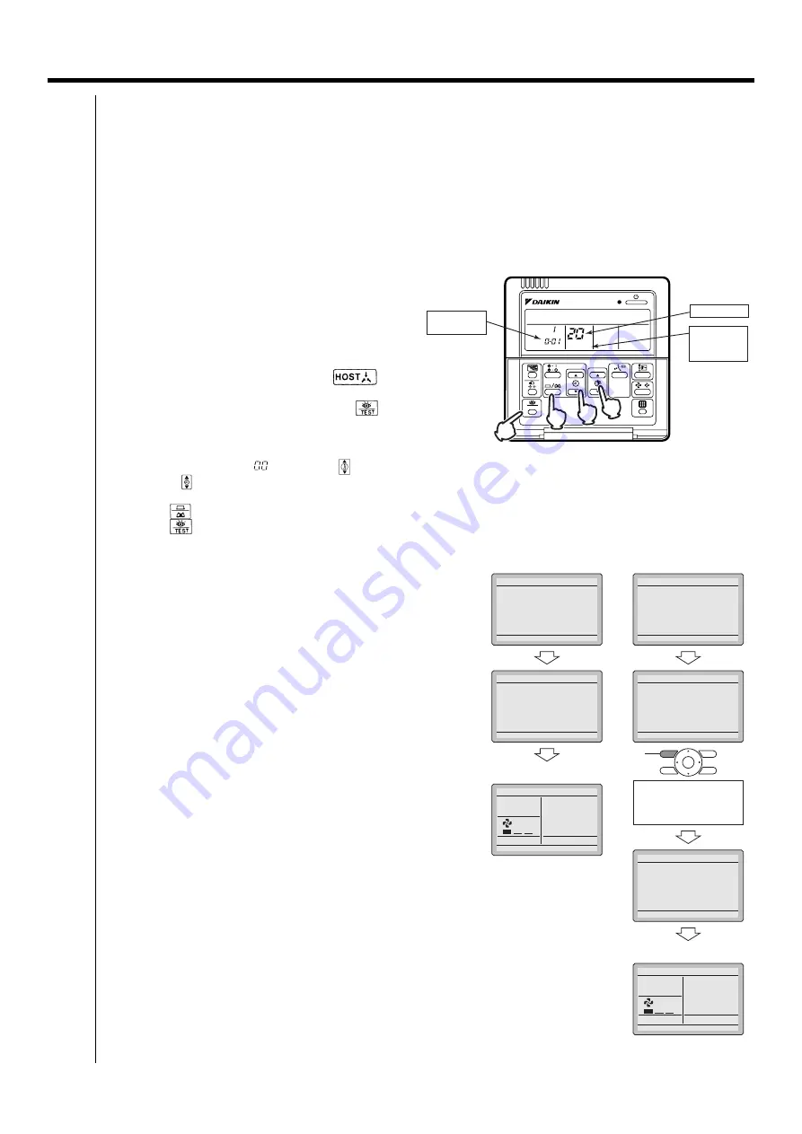
5.2.1 Wired Remote Controller <BRC1C62>
1. Turn ON the power of the indoor unit and unified ON/
OFF controller. (Unless the power is ON, no setting
can be made.)
Check that the installation and electrical wiring are
correct before turning the power supply ON.
When the power supply is turned ON, all LCD appear
once and the unit may not accept the operation for
about one minute with the display of “
”
flashing (an interval of ON, ON, and OFF).
2. While in the normal mode, hold down the “
”
button for a minimum of 4 seconds.
The remote controller will enter the FIELD SETTING
MODE.
3. Select the MODE No. “
” with the “
” button.
4. Use the “
” button to select the group address. for each group.
(Group address increase in the order of 1-00, 1-01, ...1-15, 2-00, ... 8-15.)
5. Press “
” to set the selected group address.
6. Press “
” to return to the NORMAL MODE.
5.2.2 Navigation Remote Controller <BRC1E61>
BRC1E61 does not have the Main/Sub switch.
1. How to confirm "Main/Sub changeover" setup.
Following are displayed after power-on. "Connection under check
Please wait for a moment"
You can confirm the current setup by the display "Main remote
controller" or "Sub remote controller" on the lower part of the screen.
2. How to change "Main/Sub changeover" setup.
While the following are displayed after power-on. "Connection
under check Please wait for a moment", press and hold 4 seconds
or longer "Operation mode selector" button of the remote
controller to be set. When the display is changed from "Main
remote controller" to "Sub remote controller", the setting is
completed and Basic screen is displayed.
Note:
Error display occurred by setting mistake.
Error code "U8": If there is only "Sub remote controller" (no "Main
remote controller" at power-on.)
→
Perform above 2. operation to change from "Sub remote
controller" to "Main remote controller".
Error code "U5": If Sub remote controller is not set at power-on in
case of one indoor unit controlled by two remote controllers.
→
Perform above 2. operation to change from "Main remote
controller" to "Sub remote controller".
Note:
Display of "Main/Sub changeover" setup is changed at the time of
"power-on".
When selecting "Main/Sub Changeover" in "Field setting" again
after setup, the display does not change (Setup changes).
To confirm setup, be sure confirm the LCD screen after power-on
accordance with above 1. How to confirm "Main/Sub changeover"
setup.
SETTING
TEST
UNIT NO.
5
2,6
4
3
MODE NO.
FIELD
SETTING
MODE
GROUP
ADDRESS.
<Main remote controller>
<Sub remote controller>
Connection under check
Please wait for a moment
Off reminder Timer
Main remote contrl
Connection under check
Please wait for a moment
Error code:U5
Main remote contrl
Connection under check
Please wait for a moment
Off reminder Timer
Main remote contrl
Connection under check
Please wait for a moment
Error code:U5
Main remote contrl
Connection under check
Please wait for a moment
Sub remote contrl
<Basic screen>
Set temperature
28
˚C
Fan
Return
Press the menu button
<Basic screen>
Set temperature
28
˚C
Fan
Return
Press the menu button
Press and hold 4 seconds
or longer the Operation
mode selector button of
sub remote controller side.
Operation mode
selector button
Summary of Contents for DCM601A51
Page 5: ...1 ED721208 1 Part 1 intelligent Touch Manager ...
Page 6: ...2 intelligent Touch Manager ED721208 ...
Page 7: ...3 ED721208 intelligent Touch Manager 1 ...
Page 8: ...4 intelligent Touch Manager ED721208 ...
Page 9: ...5 ED721208 intelligent Touch Manager 1 ...
Page 10: ...6 intelligent Touch Manager ED721208 ...
Page 11: ...7 ED721208 intelligent Touch Manager 1 ...
Page 12: ...8 intelligent Touch Manager ED721208 ...
Page 13: ...9 ED721208 intelligent Touch Manager 1 ...
Page 14: ...10 intelligent Touch Manager ED721208 ...
Page 15: ...11 ED721208 intelligent Touch Manager 1 ...
Page 16: ...12 intelligent Touch Manager ED721208 ...
Page 17: ...13 ED721208 intelligent Touch Manager 1 ...
Page 18: ...14 intelligent Touch Manager ED721208 ...
Page 40: ...36 7 2 Error Code on Initial Setting and Wiring Troubles Fundamental of DIII NET ED721208 ...
Page 403: ......


