T
ROUBLESHOOTING
T
ROUBLESHOOTING
C
HAPTER
9
9-4
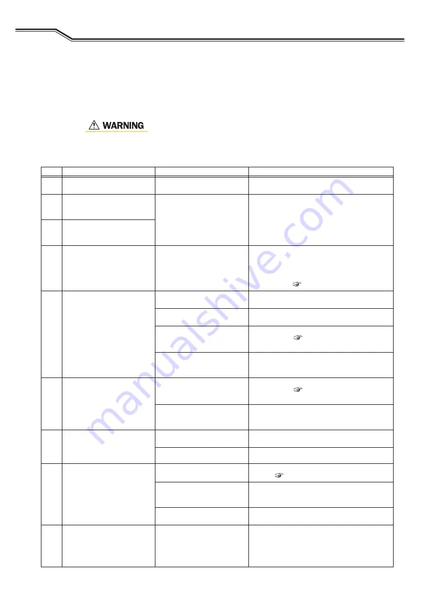
9.2 Troubleshooting
This section explains the typical problems other than the error codes, their causes, and how to cope with
them.
Check the table below before requesting repair service.
• Before inspecting the welding power source, make sure to read "8.1
-
No.
Problem
Possible cause
Corrective action
1
The power switch has tripped.
Leak has occurred in the
welding power source.
DO NOT turn on the power switch. Contact your
dealer.
2
The power LED switch does not
light even when the power
switch is turned on.
The primary power source is not
supplied.
Supply the primary power source between 340 to
460 V.
3
Nothing is displayed on the left/
right digital meters even when
the power switch is turned on.
4
"Temperature WARNING" LED
lights and an error code is
displayed when the power
switch is turned on.
The protection circuit has been
activated due to temperature
error.
Leave it untouched (with the power on) and operate
the cooling fan for 10 minutes or more, and then
turn off the power.
After the above, clean dusts inside the welding
power source. (
5
Shielding gas is not flowing.
The valve of gas cylinder is
closed.
Open the gas valve.
The pressure of gas cylinder is
insufficient.
Replace the gas cylinder.
Setting/handling of the external
inputs is not correct.
Check that the setting of internal functions F29 to
F32 is correct. (
-
The external input cables are
disconnected/short-circuited.
Check that there is no abnormality in the cables
connected to the external input terminal block.
If any, repair/replace the cables.
6
Shielding gas does not stop
flowing.
Setting/handling of the external
inputs is not correct.
Check that the setting of internal functions F29 to
F32 is correct. (
-
The external input cables are
disconnected/short-circuited.
Check that there is no abnormality in the cables
connected to the external input terminal block.
If any, repair/replace the cables.
7
Arc does not generate even
when the setting of welding
conditions is correct.
(w/o no-load voltage)
Connection of the torch cable is
loose.
Securely connect the torch cable.
The torch switch is broken.
Check that the torch switch works normally.
8
Setting of current/voltage is not
possible.
The automatic machine mode is
selected.
Check that the setting of internal functions F4 is
correct. (
An analog remote control
(optional) is connected.
When an analog remote control (optional) is
connected, the setting of the remote control has
priority.
The encoder is broken.
The printed circuit board PCB2 (P30086R00)
needs to be replaced. Contact your dealer.
9
The mode does not change even
when the CRATER-FILL key is
pressed.
(The LED position does not
change.)
The internal function F4, F48 or
F51 is set to "ON".
Turn the settings to "OFF".


