background image

User’s Manual 

22 

Setting 

This  chapter  introduces  how  to  configure  and  view  the  radar  information,  including  settings 
about radar, network, event, storage, and system. 


Radar 

You  can  make  configurations  about  radar  such  as  setting  video  and  snapshot  parameters, 
adding PTZ cameras, doing radar and camera linkage, managing protection zone, and setting 
IVS. 

4.1.1 

Video 

You can set video stream, snapshots, overlay, and storage path. 

4.1.1.1 

Video Stream 

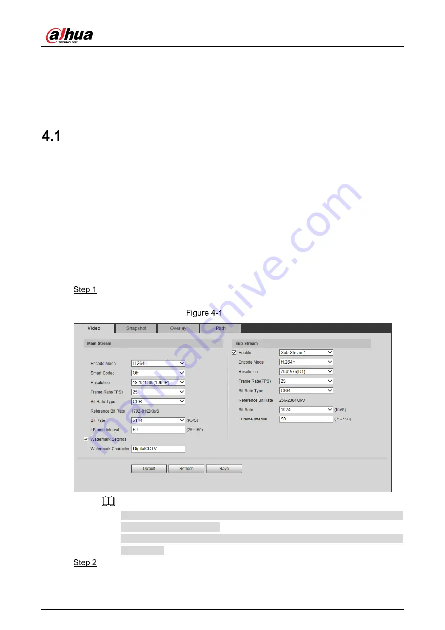
You can set the main stream and sub stream of live videos. 


Select 

Setting > Radar Settings > Video > Video

The 

Video

 interface is displayed. See Figure 4-1. 


Adjust pitch angles 


Video  stream  configuration  interface  might  vary  with  different  devices,  and  the 
actual interface shall prevail. 


Default values might vary with different video streams, and the actual interface 
shall prevail. 


Configure parameters as needed. For details, see Table 4-1.

Summary of Contents for DH-PFR4K-D300

Page 1: ...Security Radar User s Manual V1 0 1 V1 0 0 ZHEJIANG DAHUA VISION TECHNOLOGY CO LTD ZHEJIANG DAHUA VISION TECHNOLOGY CO LTD...

Page 2: ...ides additional information as the emphasis and supplement to the text Revision History Version Revision Content Release Time V1 0 1 Delete previous Figure 4 65 February 2020 V1 0 0 First release Dece...

Page 3: ...re is any doubt or dispute please refer to our final explanation Upgrade the reader software or try other mainstream reader software if the manual in PDF format cannot be opened All trademarks registe...

Page 4: ...tilated place and do not block the ventilation of the device Operate the radar within the rated range of power input and output Do not dissemble the radar Transport use and store the radar under the a...

Page 5: ...e List 13 PTZ Control 13 3 Playback 15 Video Playback 15 3 1 1 Playing Video 16 3 1 2 Record Types 17 3 1 3 Auxiliary Functions 17 3 1 4 Record Files 17 3 1 5 Clipping Records 18 3 1 6 Time Format of...

Page 6: ...4 1 Schedule 60 4 4 2 Destination 63 4 4 3 Record Control 66 System 67 4 5 1 General 67 4 5 2 Date Time 68 4 5 3 Account 69 4 5 4 Onvif User 74 4 5 5 Safety 75 4 5 6 Firewall 82 4 5 7 Default 84 4 5 8...

Page 7: ...nly two connection methods between the radar and PC See Figure 1 1 and Figure 1 2 Connected by network cable Connected through router or switch Radar models presented in the figures are for reference...

Page 8: ...sfully connected the Device Initialization interface is displayed See Figure 1 3 Device initialization Set the password See Figure 1 4 The password should consist of 8 to 32 non blank characters and c...

Page 9: ...efault and you can disable it We recommend you to enter the email address to guarantee normal use of the radar Click Save The End User License Agreement interface is displayed See Figure 1 5 End user...

Page 10: ...x as needed and then click Next The Online Upgrade interface is displayed See Figure 1 7 Online upgrade Read on screen notifications select Auto check for updates check box as needed and then click Ne...

Page 11: ...dard as needed and then click Save The login interface is displayed See Figure 1 9 Login 1 2 2 First time Login You need to download and install the plug in for the first time login Enter username and...

Page 12: ...again You can set the allowed wrong password times in Setting Event Abnormality Illegal Access For details see 4 3 2 3 Illegal Access Download and install the plug in according to the on screen instr...

Page 13: ...get it Open IE browser enter the IP address of the radar in the address bar and then press Enter The login interface is displayed See Figure 1 12 Login Click Forget password The Prompt interface is di...

Page 14: ...urs after you get the security code otherwise it will be invalid If the security code is not used twice continuously for the third time the system will prompt that you fail to acquire the security cod...

Page 15: ...2 non blank characters and contain at least two types of characters among upper case lower case number and special characters excluding Follow the password strength prompt to set a password with high...

Page 16: ...ve view Table 2 1 Live view parameter descriptions No Description No Name 1 Set encoding mode 2 Video tool 3 Adjust video window 4 Function tabs 5 Function options 6 Device list Encoding Configuration...

Page 17: ...modify the storage path in Setting Radar Settings Video Path For details see 4 1 1 4 Storage Path 5 Record Click the icon to take record of the live video 6 Audio Click the icon to mute or unmute the...

Page 18: ...See Figure 2 5 System menu Function Options Click each icon to use different functions such as manual positioning and taking snapshots and records For details see Figure 2 6 and Table 2 4 Function op...

Page 19: ...ns No Name Description 1 Main Stream Under the selected stream media protocol use main stream to monitor and store video Main stream is applied in live view and record storage by default Click the ico...

Page 20: ...ns Name Description Direction Support eight directions Up down left right upper left upper right lower left and lower right Quick position Click the icon draw a box on radar s live interface and then...

Page 21: ...s web Before playback you need to configure parameters such as record and snapshot schedule storage method and record mode For details see 4 4 Storage Click Playback tab The Playback interface is disp...

Page 22: ...ds 7 Time format of the time bar For details see 3 1 6 Time Format of the Time Bar 3 1 1 Playing Video You can do video playback operations such as playing and pausing stopping fast and slow playing a...

Page 23: ...zoom in or zoom out the image and take a snapshot For details see Figure 3 5 and Table 3 3 Auxiliary functions Table 3 3 Auxiliary function icon descriptions No Name Description 1 Digital Zoom For det...

Page 24: ...ds You can clip the selected record as needed The function column is displayed as Figure 3 7 Clip record Select start time of clipping on time bar which should be within time range of the record Move...

Page 25: ...ns Icon Description Click the icon to display the time bar in 24 hour mode Click the icon to display the time bar in 2 hour mode Click the icon to display the time bar in 1 hour mode Click the icon to...

Page 26: ...urce and date and then you can play back snapshots On the calendar the date with blue background means the current date has snapshots See Figure 3 11 For parameter descriptions see Table 3 7 Select sn...

Page 27: ...on Description Click the icon to search all snapshot files within the start time and end time of selected date Click icon to download snapshot file to local storage Click icon to return to calendar in...

Page 28: ...setting IVS 4 1 1 Video You can set video stream snapshots overlay and storage path 4 1 1 1 Video Stream You can set the main stream and sub stream of live videos Select Setting Radar Settings Video V...

Page 29: ...mode Reference Bit Rate The most suitable bit rate range recommended to users according to the set resolution and frame rate Bit Rate The value is the upper limit of the stream in VBR mode In CBR mode...

Page 30: ...esolution of snapshot under main stream by default Quality Set the image quality There are six levels from 1 to 6 6 is the best The higher the level is the larger the picture will be Interval Set snap...

Page 31: ...User s Manual 25 Channel title Time title...

Page 32: ...User s Manual 26 OSD information Font...

Page 33: ...itle box to adjust the display position Time Title Enable or disable Time Title to be overlaid on the video image By selecting Week Display check box the day will be displayed Drag the Time Title box...

Page 34: ...can set storage paths of snapshots and records taken from live view and snapshots downloads and video clips from playback Select Setting Radar Settings Video Path The Path interface is displayed See F...

Page 35: ...11 Add PTZ camera Enter IP address camera name type username and password Click Save Switch to to enable alarm track linkage between the radar and the selected camera 4 1 3 Linkage You can import a ma...

Page 36: ...map See Figure 4 13 Import a map Click Choose to select a map and then import the map Maps of png jpg and bmp format can be imported Cut the map according to the detection range of the radar Drag the...

Page 37: ...culate Map Size The system will automatically get the map width and height Click Next The Radar Positioning interface is displayed See Figure 4 14 Radar positioning Configure radar position Click and...

Page 38: ...cking system and you can skip this setting as needed Log in to the linked PTZ camera Enter the username and password of the camera and then click OK See Figure 4 15 The Radar Calibration interface is...

Page 39: ...can also double click the map to enter full screen and drag the to be positioned more accurately Move the monitoring image of the camera to where the radar coordinate is set by clicking PTZ direction...

Page 40: ...nable region management Double click the name under the Name column to modify the region name Configure the region type Double click Pre warning under the Type column to select region type from Alarm...

Page 41: ...be triggered when it occurs during the defined period The time period in green on the timeline is armed Method one Click Setting of the day you want to set Directly press and drag the left mouse butto...

Page 42: ...l the camera to record and the record rules of the camera are invalid When the alarm track is disabled the radar will not control the camera and the camera will record under its own recording rules Re...

Page 43: ...rning area Shield area is subject to pre warning area when they overlap Shield area The target will not be tracked and its trace will not be displayed in the shield area When there are areas with obje...

Page 44: ...ne interference signals from other devices in the same frequency band lead to radar trajectory clutter and make false negatives and misinformation increased Detection Region Select from two detection...

Page 45: ...meter descriptions Name Description Environment Mode General Apply to detection regions without shrubs except large barriers such as cars Shrub Apply to detection regions with trees shrubs and other s...

Page 46: ...k Set corresponding gateway and subnet mask if there is a router in the network Select Setting Network TCP IP The TCP IP interface is displayed See Figure 4 23 TCP IP Configure parameters See Table 4...

Page 47: ...It is enabled by default During restarting you will have no more than 2 minutes to configure the device IP address by a ping packet with defined length the server will be turned off in 2 minutes or it...

Page 48: ...ttp IP address in the browser address bar to log in 4 2 2 Port This section introduces configurations of the maximum number of users that can connect to the radar simultaneously and value of each port...

Page 49: ...mart phone you need to turn off the audio and then set the codec mode to H 264B and resolution to CIF URL format example rtsp username password ip port cam realmonitor channel 1 subtype 0 Among that U...

Page 50: ...tches your IP address and the matching relation refreshes in real time You can always visit your device with the same domain name no matter how much your device IP address changes Before making config...

Page 51: ...he DDNS service provide You need to register an account with username and password on the DDNS service provider s website Password Interval The update cycle of the connection between the radar and the...

Page 52: ...and the sender information Sender Sender s email address Authentication Select Authentication from None SSL and TLS TLS is set by default For the detailed configuration see Table 4 13 Title Enter no m...

Page 53: ...5 You need to enable SMTP service in your mailbox Click Save 4 2 6 UPnP Universal Plug and Play a protocol that establishes mapping relation between intranet and Internet This function enables you to...

Page 54: ...ort automatically You cannot modify mapping relation Select Start Device Discover as needed Click Save to make the configurations valid 4 2 7 SNMP Simple Network Management Protocol which can be used...

Page 55: ...r s Manual 49 SNMP 2 Select SNMP version to enable SNMP In the Trap Address enter the IP address of the PC that has MIB Builder and MG SOFT MIB Browser installed and leave other parameters as the defa...

Page 56: ...t port of the trap information sent by the software agent of the radar Read only Username The name is public by default You can enter number letter and underline to form the name Read write Username T...

Page 57: ...r The Bonjour interface is displayed See Figure 4 31 Bonjour Select Enable and then configure server name Click Save In the operating system and clients that support Bonjour follow steps below to visi...

Page 58: ...the range is 1025 65500 Click Save The multicast configuration of TS is similar to RTP and you can refer to the previous steps 4 2 10 802 1x 802 1x port based network access control protocol supports...

Page 59: ...etwork QoS The QoS interface is displayed See Figure 4 34 QoS Configure parameters See Table 4 17 Table 4 17 QoS parameter descriptions Parameter Description Realtime Monitor Configure the priority of...

Page 60: ...orner of the app on the Device interface Scan the QR code on the P2P interface Follow on screen instructions to finish the configurations 4 2 12 2 ONVIF The ONVIF Open Network Video Interface Forum al...

Page 61: ...are triggered Select Setting Event Alarm The Alarm interface is displayed See Figure 4 37 Alarm linkage Select Enable check box to enable the alarm linkage and configure parameters as needed Configure...

Page 62: ...ime period Select All or the check box of any other day and the set time period will apply to the selected days You can set 6 time periods per day Click Save to return to the Alarm interface Set other...

Page 63: ...from 10 s to 300 s after the alarm is ended Send Email By selecting Send Email the system automatically sends email to the specified mailbox when the alarm is triggered You can configure the mailbox i...

Page 64: ...nfigure the free space percentage and if the free space in the SD card is lower than the defined percentage the alarm is triggered Click Save 4 3 2 2 Network When any abnormality happens to the networ...

Page 65: ...Illegal access parameter descriptions Parameter Description Enable Select Enable check box to enable to network card abnormality detection Login Error The number of times that the login password is a...

Page 66: ...normality Scene Changing The Scene Changing interface is displayed See Figure 4 43 Scene changing Select Enable check box to enable scene changing alarm and then configure other parameters as needed F...

Page 67: ...nd then press and drag the left mouse button to draw the time period for alarm record on the timeline Method two Enter an actual time period Click Setting of the day you want to set The Setting interf...

Page 68: ...ts or stops taking snapshot as scheduled Select Setting Storage Schedule Snapshot The snapshot schedule interface is displayed See Figure 4 46 Snapshot schedule Configure time periods For details see...

Page 69: ...n type and detection period For details see 4 4 1 1 Record Schedule Click Save Record and snapshot will be taken according to the set holiday schedule for the selected days 4 4 2 Destination This sect...

Page 70: ...twork Attached Storage Click Save 4 4 2 2 Local Display the internal SD card information You can set it as read only or read write you can also hot swap or refresh it Select Setting Storage Destinatio...

Page 71: ...ess The IP address of the FTP server Port The port number of the FTP server Username The username to log in to the FTP server Password The password to log in to the FTP server Remote Directory The des...

Page 72: ...rver Message Block Provide shared access for clients and the server Server Address The IP address of the NAS server Remote Directory The destination path in the NAS server Click Save 4 4 3 Record Cont...

Page 73: ...n the disk is full You can select from Stop The system stops recording when the disk is full Overwrite The system overwrites the oldest files and keeps recording when the disk is full Record Mode Manu...

Page 74: ...ST Daylight Saving Time and NTP Network Time Protocol server Select Setting System General Date Time The Date Time interface is displayed See Figure 4 54 Date Time Configure Date Time parameters See T...

Page 75: ...bers letters and underline The password must consist of 8 to 32 non blank characters and contain at least two types of characters among upper case lower case number and special character excluding Fol...

Page 76: ...and password Anonymous users only have live view authority Under Anonymous Login you can log in with other account after clicking Logout Adding a User You can add users to the group and configure user...

Page 77: ...user can be in only one group at a time and the group users can own authorities within group authority range It is recommended to give fewer authorities to normal users than premium users Optional Cli...

Page 78: ...User s Manual 72 Restricted login Click Save Modifying a User Click of the selected user The Modify User interface is displayed See Figure 4 58...

Page 79: ...ord check box Enter the old password new password and then confirm the password Click Save Deleting a User Click to delete the added user 4 5 3 2 Group You have two groups named admin and user by defa...

Page 80: ...ils see 4 5 3 1 User Deleting a Group For details see 4 5 3 1 User 4 5 4 Onvif User You can add delete and modify Onvif users Select Setting System Account Onvif User The Onvif User interface is displ...

Page 81: ...ming Protocol RTSP ensures the safety of the streaming media during transmission Select Setting System Safety RTSP Authentication The RTSP Authentication interface is displayed See Figure 4 62 RTSP Au...

Page 82: ...n enable SSH authentication to perform safety management Multicast Broadcast Search Enabled by default When multiple users watch the live video simultaneously through network they can find your device...

Page 83: ...ficate and then you can connect through HTTPS with your PC The HTTPS can ensure safety of data communication user information and radar with reliable technology Create a certificate or upload the auth...

Page 84: ...Download to download root certificate The Save As dialog box is displayed See Figure 4 66 Download certificate Select storage path and then click Save Double click the RootCert cer icon The Certifica...

Page 85: ...User s Manual 79 Certificate Click Install Certificate The Certificate Import Wizard interface is displayed See Figure 4 68 Certificate import wizard...

Page 86: ...xt Select Trusted Root Certification Authorities See Figure 4 69 Store certificate Click Next The Completing the Certificate Import Wizard interface is displayed See Figure 4 70 Complete certificate i...

Page 87: ...ssfully If you select Install Signed Certificate follow the steps below Select Setting System Security HTTPS The HTTPS interface is displayed Click Browse to select signed certificate path and certifi...

Page 88: ...oin By enabling Prevent Semijoin function the radar can provide service normally under Semijoin attack You cannot add IP MAC address of the radar to the trusted or banned list You cannot set port numb...

Page 89: ...the host to be added All IP addresses Set all IP addresses in trust list or banned list IP Version IPv4 Enter IP address in IPv4 format such as 192 108 1 125 IPv6 Enter IP address in IPv6 format such...

Page 90: ...t system configuration file to make quick configuration or recover system configuration The map you imported in linkage configuration cannot be imported or exported Select Setting System Import Export...

Page 91: ...1 days When you enable and confirm the Auto Delete Old Files the deleted files cannot be restored Be careful Click Save 4 5 10 Upgrade You can upgrade the system to the latest version to improve radar...

Page 92: ...verify device legality and send upgrade messages If there is any upgrade available click Upgrade and then the system starts upgrading Click Manual Check and you can check for upgrade manually Informat...

Page 93: ...configuration files Data Include configuring disk type erasing data hot swap FTP status and record mode Event Record events such as video detection smart plan alarm and abnormality Include event start...

Page 94: ...te log Select Enable check box to enable the remote log function Set the IP address port and device number as needed Click Save You can click Default to restore the settings 4 6 4 Online User You can...

Page 95: ...larm Table 5 1 Alarm parameter descriptions Parameter Name Description Alarm Type Disk Full Select to record the alarm when disk is full Disk Error Select to record the alarm when disk malfunctions Ex...

Page 96: ...ill be recorded automatically icon disappears when you click Alarm tab Note If you are in Alarm interface when the alarm is triggered icon will not be displayed but the alarm will be recorded Alarm To...

Page 97: ...User s Manual 91 6 Logging out Click Logout tab and then the system goes back to login interface See Figure 6 1 Login...

Page 98: ...e the auto check for updates function to obtain timely information of firmware updates released by the manufacturer We suggest that you download and use the latest version of client software Nice to h...

Page 99: ...ypted Transmission If your audio and video data contents are very important or sensitive we recommend that you use encrypted transmission function to reduce the risk of audio and video data being stol...

Page 100: ...94 Establish the 802 1x access authentication system to reduce the risk of unauthorized access to private networks Enable IP MAC address filtering function to limit the range of hosts allowed to acce...

Page 101: ...User s Manual...

Reviews: