8
D-Link DCS-7510 User Manual
Section 1 - Product Overview
Hardware Overview
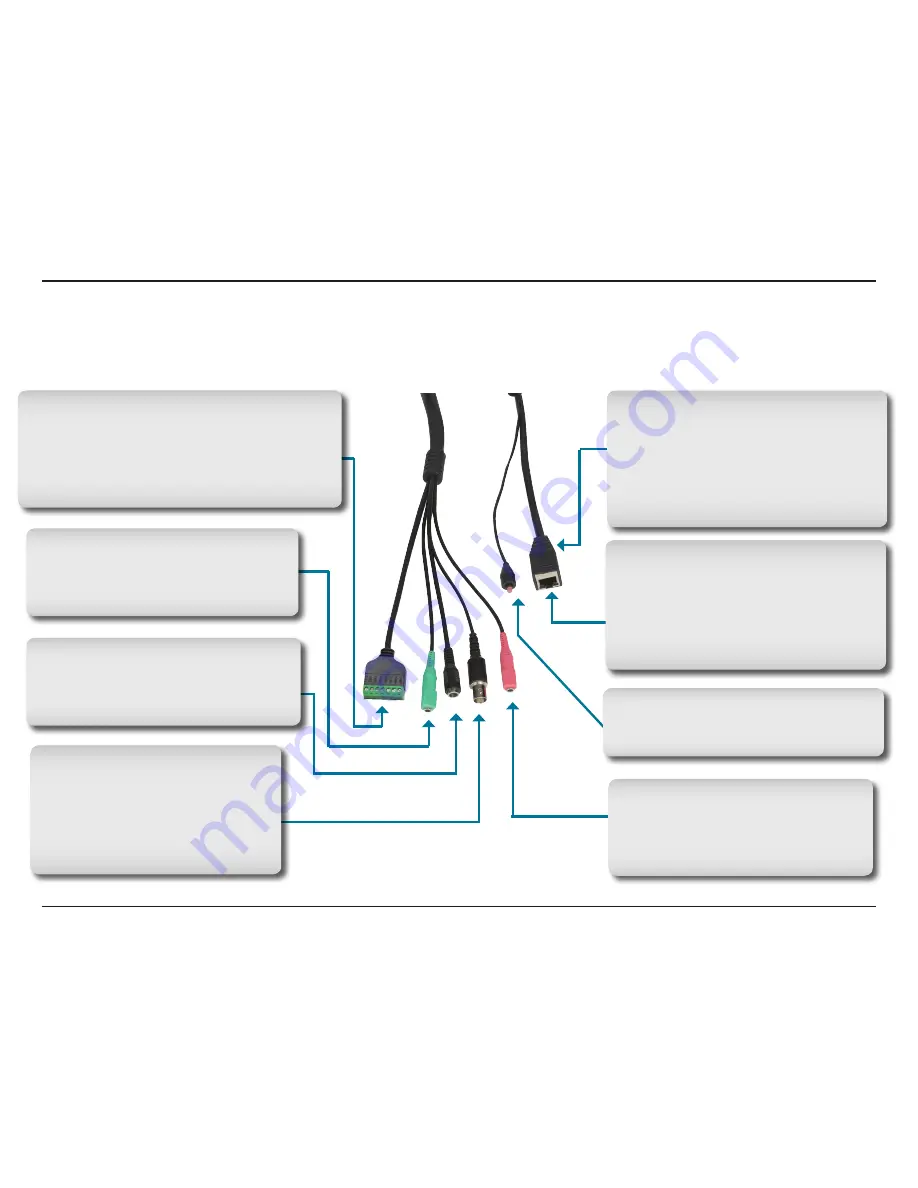
Connectors
Reset Button
Resets the camera to factory defaults
when pressed for 10 seconds.
Microphone Connector
Connect an external microphone to the
microphone connector to hear what is
happening near your camera.
Link/Power LEDs
Lights up and changes color to indicate
the Link and Power status of your camera.
Green LED indicates Link up/Link down/
Traffic
Red LED indicates Power on/Power off
DC Power Connector
Attach the Power Adapter to the DC
connector and connect the power adapter
to a power outlet.
I/O Connector
The DCS-7510 offers a 8 pin-contact terminal block.
Two pairs are for input, one pair for output and
RS485 terminals. The connector provides a physical
interface to send and receive digital signals to and
from a variety of external devices.
Audio Out Connector
Speakers (not included) may be
connected to the camera for a 2-way audio
communication.
BNC
The BNC connector is used for
professional video connections. It
benefits users who integrate digital
IP cameras into a traditional system
(CCTV) for both analog and digital video
streaming purposes.
Ethernet Cable Connector (PoE)
Plug the Ethernet cable into the RJ-45 PoE
connector. When connected to a PoE switch,
the built-in 802.3af compliant Power over
Ethernet (PoE) eliminates the need for a
nearby power outlet, giving you the freedom
to place the camera anywhere.
Summary of Contents for DCS-7410
Page 1: ......
Page 19: ...19 D Link DCS 7510 User Manual Section 2 Installation Click Next Click Next ...
Page 20: ...20 D Link DCS 7510 User Manual Section 2 Installation Click Next Click Next ...
Page 21: ...21 D Link DCS 7510 User Manual Section 2 Installation Click Next Click Next ...
Page 23: ...23 D Link DCS 7510 User Manual Section 2 Installation Installing Click Finish ...


