


CY3280-MBR2 CapSense Express with SmartSense Auto-Tuning Kit Guide, Doc. # 001-71857 Rev. *C
27
Kit Operation
Figure 3-20. Button Controlled LED Effects Pattern
3.2.11
System Diagnostics
3.2.11.1
Enable System Diagnostics
The System Diagnostics feature is enabled in the CY8CMBR2110 CapSense controller by default;
no change is needed in the kit. This feature sends out a 5-ms pulse on the GPO corresponding to a
faulty sensor. The GPO pins are connected via the 44-pin expansion connector, which can be
probed to observe the 5-ms pulse. See
for details of the expansion
connector and to know the pin associated with each button and GPO. The pin number can be
counted starting from the lower pin on the USB connector side, as shown in the following figures.
Note that all odd numbered pins are at the bottom half of the connector.
The system diagnostics feature can also be observed in the EZ-Click Customizer Tool.
3.2.11.2
Test System Diagnostics - CapSense Button Short to Ground
Follow these steps:
1. Touch the power button to turn off the kit.
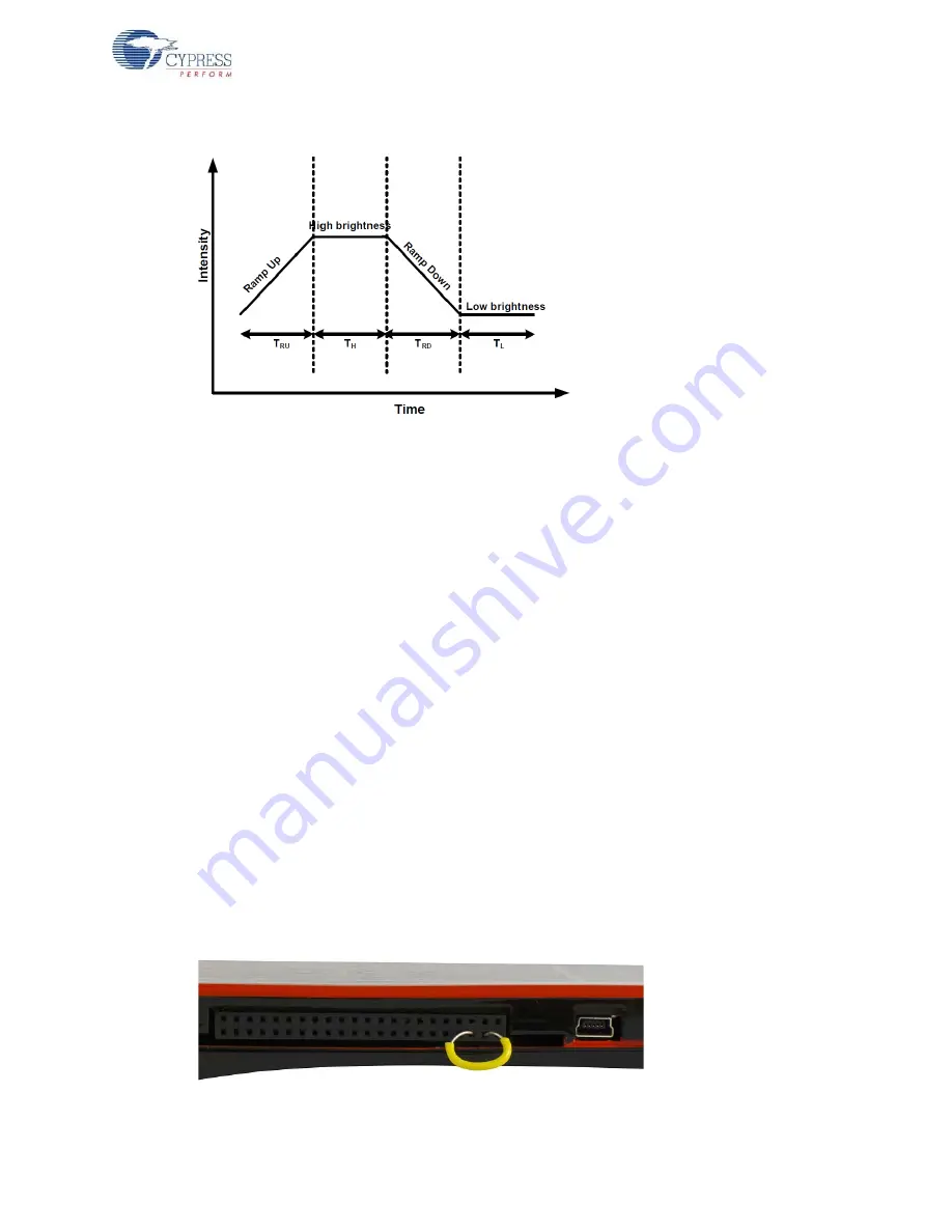
2. Connect a wire between pin #3 and pin #5 of 44-pin expansion connector. This shorts the button
#5 sensor to ground.
3. Touch the power button to turn on the kit.
The CapSense controller executes the System Diagnostics routine on power up and detects the sen-
sor shorted to ground. Observe a pulse of 5 ms width on the GPO #5 pin, which is also visible on the
corresponding LED. This indicates that button #5 is shorted to ground. The CapSense controller dis-
ables the button sensors that are shorted to ground. Touch button #5 and see that the corresponding
LED is not turned on. Other buttons work normally.
Figure 3-21. Shorting Button #5 (pin #3) to Ground (pin #5)


