background image

part

Cf1/miami part no

Manhattan part no

DOOR GLASS ASSEMBLY

cf1

Man 1

Gas control

cf2

Man 2

handset

cf3

Man 3

receiver

cf4

man4

log set

cf5

man5

Driftwood set

cf6

man6

pebbles

cf7

man7

granules

cf8

man8

Bark chipping

cf9

man9

Ods pilot assembly seagas

cf10

man10

Injector 440

cf11

man11

ODS pilot assembly SIT

CF12

man12

26                                                                          issue 5

23:4
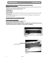
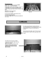
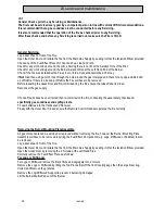
Changing the Gas Control.
Follow Section 23:1 Removing the Burner Mounting Plate Assembly. 

If Logs or Driftwood is being used remove and retain the 3 screws securing the Log Support to prevent it becoming 
damaged  
Remove and retain the 3 screws securing the Air Guide.

With the Burner Mounting Plate Assembly upside down disconnect the Electrode Lead from the Pilot Electrode, 
disconnect the Pilot Pipe from the back of the Main Control and the Thermocouple from the Main Gas Control. 
Disconnect the Outlet/Injector Pipe and the Main Inlet Pipe.
Remove and retain the 2 screws securing the Main Control.
Fit the new Control and replace all parts in reverse order. 
For refitting the Fuel Bed components see relevant section
Check all faults have been corrected then re-commission the fire, conducting the usual safety checks and specifically 
gas soundness and spillage tests.
Fit new batteries into the Handset and Receiver
Finally with the Outer Door Closed ensure the Remote Control Handset operates the fire correctly.

Summary of Contents for Boston Cf1

Page 1: ...f1 and MANHATTAN Inset Conventional Flue Fire USER INSTALLATION AND SERVICING INSTRUCTIONS FOR USE WITH NATURAL GAS G20 20 mbar For use in GB and IE CE THESE INSTRUCTIONS MUST BE LEFT WITH THE USER FO...

Page 2: ...lation requirements 8 8 Technical data 9 9 Dimensions 10 10 Contents of fixing kit 10 11 Appliance location 11 12 Flue requirements and builders opening requirements 12 13 Surround requirements 13 14...

Page 3: ...for the protection of young children the elderly the infirm and pets 1 5 DO NOT burn paper or rubbish in the fire 1 6 It is important for the safe operation and to maintain efficiency that the fire is...

Page 4: ...t does not light turn the knob back to off setting and repeat the operation This may take several attempts on the first lighting Pilot position shown above at cut out on left side Fig 2 1b SAFETY The...

Page 5: ...ll not be able to relight the fire or turn the knob for at least 10seconds as the control as a built in safety lock Do not force the knob as this will damage the control Wait until the safety lock as...

Page 6: ...you It is recommended that Alkaline Long Life Batteries be used Over time the red light will reduce in brightness indicating that the batteries require changing We recommend that the batteries in the...

Page 7: ...ieces it is indicating that the Fire requires Servicing 3 5 Due to the nature of the convection air flowing over the fire the walls of the room directly around and above the fire may become discoloure...

Page 8: ...t and ensure it is sealed in completely on four sides either using the foam strips or preferably sand and cement to ensure a good seal into the builders opening BS BS BS BS BS 5871 8303 5440 PART 1 54...

Page 9: ...e parts This fire must not be installed in a room that contains a bath or shower This fire cannot be installed onto a combustible wall All combustible materials must be removed from the area shown in...

Page 10: ...mm 290mm 275mm 290mm MINIMUM OPENING DEPTH 285mm 340mm 285mm 340mm The only difference between the 2 appliances is the manhattan is 150 mm taller Warning slight dimensional changes may occur without n...

Page 11: ...if placed to close to the appliance WARNING A suitable guard should be used for he protection of children the elderly and the infirm The fire must be fitted against a non combustible surface which mus...

Page 12: ...t of the flue must be at least 3 metres A Purpose Made Builders Opening With a Conventional Stone Flue With a minimum cross sectional dimension of 175mm 7 and a minimum effective height of 3 metres Fi...

Page 13: ...of carpets sliding on to the hearth If the hearth as an up stand the base of the fireplace opening will have to be raised the height of the up stand to ensure the outer door can still be opened See F...

Page 14: ...rough masonry Only use a rigid or semi rigid metal tubing of 8mm can be used A combined Restrictor Elbow with Pressure Test Point is supplied with the fire and comes complete with a 8mm nut and olive...

Page 15: ...rame must be sealed so no air can pull through it after installation all the flue pull must be made through the fire diverter and from no other place The fire should now be sealed to the sealing frame...

Page 16: ...Fuel Fig 17 1 Important Ensure the Burner Ceramic Base Pad is fitted the Right way around with the central slot at the rear Normally factory fitted Ensure no granules are placed on top of the Burner...

Page 17: ...ould be made to the relative Fuel Effect Layout Sections in these Instructions please read thoroughly before proceeding When placing Logs or Driftwood Pieces over the burner ensure that they are sitti...

Page 18: ...e Pad Ensure no granules fall onto the Pilot Carefully place the granules around the front of the Metal Air Guide and around the sides of the rear log As shown in Fig 18 3 Do not block air inlets on f...

Page 19: ...ch on the Large Rear Log Driftwood As shown Fig 18 6 Fig 18 6 18 7 Fitting Log or Driftwood No5 Fit Log or Driftwood No5 next to the last Piece ensuring the hole in the base locates Onto the metal peg...

Page 20: ...nd clear of any Vermiculite and or Bark Chips Check that the Glass Door is clean then seal closed with the 2 screws Fig 18 9 19 PEBBLE SET The log support bracket must be removed before the pebbles ca...

Page 21: ...marked D underneath The four pebbles marked L sit at the rear of the base pad and on to the fibre strip as left above The final 2 pebbles sit at the side as above The 5 pebbles marked D sit on the bru...

Page 22: ...illage If this corrects the problem then additional ventilation Air Brick will be required Seek expert assistance with all these issues as the customer will need to be advised 22 instruct the user 22...

Page 23: ...is the Fire will have to be removed Before resealing the Glass Door and Re commissioning the fire ensure the Glass Panel is Clean Reconnect the gas supply Check all faults have been corrected then re...

Page 24: ...eces following the relevant instructions 23 2 Removing the Fire Note This should only be required for removal of Debris or to check the condition of the Flue Chimney The fire is installed into a speci...

Page 25: ...d Receiver Finally with the Outer Door Refitted and Closed ensure the Remote Control Handset operates the fire correctly 23 3 Changing the ODS Pilot Assembly The ODS Pilot Assembly is not a Serviceabl...

Page 26: ...screws securing the Air Guide With the Burner Mounting Plate Assembly upside down disconnect the Electrode Lead from the Pilot Electrode disconnect the Pilot Pipe from the back of the Main Control and...

Page 27: ...ders opening so as to not risk damaging the fire surround If any gaps are present they must be sealed with either fire cement or ideally a high temperature silicone sealant FIXING POINTS ON FRAME ONCE...

Page 28: ...ETURN TO SECTION 16 2 AND CONTINUE WITH THE INSTALLATION AIR SUPPLY MUST BE KEPT CLEAR ONCE INSTALLATION IS COMPLETE THE TRIM IS FITTED BY PLACING THE TRIM INTO PLACE AND SECURING USING MAGNETS SUPPLI...

Reviews: