8
1)
POWER
: Light on when power is supplied.
2)
LINK
: Light on when LAN Cable is connected to S-160.
3)
LAN
: Light on when connected to Network
.
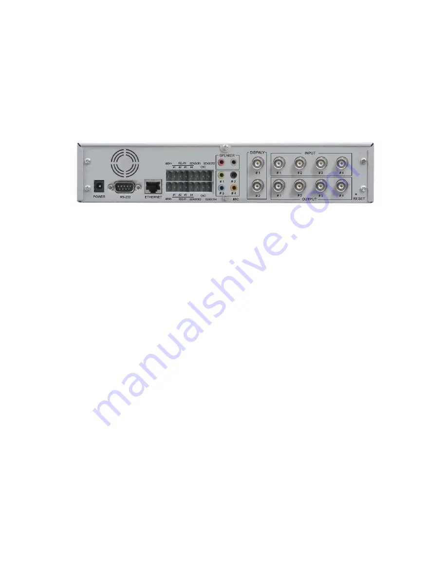
1.2.2 Rear view
1)
Power Supply
: Excusive (provided) Adapter only
2)
Micro Phone Port
: To connect Microphone
3)
Speaker Port
: To connect Speaker
4)
Relay Output
: Output port with embedded Relay.
5)
Sensor Input
: Sensor Input port, to be set in Inner Setting and to be used without regard to N/C or N/O
6)
RS485 Port
: Input / Output Port of RS485
7)
Serial Port
: To control of Pan/Tilt/Zoom of Camera and connect to PLC or outer Devices (RS232)
8)
Video In
: Input port to connect with signal output from Camera, VTR, Quad, DVR
9)
Video Out
: Output of the same video signal that put into the Video Input Port.
10)
LAN
: LAN Cable port for Internet to connect to Internet
11)
Hardware Reset
: To initialize basic setting. Push and hold for seconds to start initialization.
①
②
③
④ ⑤
⑥
⑦
⑧
⑨
⑩
⑪
⑫
Summary of Contents for S-160
Page 1: ...1 Network A V Server S 160 User s Manual Version1 0 ...
Page 6: ...6 1 Feature ...
Page 9: ...9 2 Installation and Video Check ...
Page 15: ...15 3 Basic Setting ...
Page 27: ...27 4 Expert Setting ...
Page 29: ...29 Pic 4 2 Administrator s Page ...
Page 48: ...48 5 Basic Use ...
Page 78: ...78 6 Network Environments ...
Page 80: ...80 7 Appendix ...


