background image

M1503 User Guide ______________________________________________________________________ Version 1.3 

Copyright © 2005-2013, Critical Response Systems, Inc.  

All Rights Reserved. 

- 13 - 

5


User Interface 

The M1503 employs a hierarchical user interface 

(“UI”)

 that includes both text and icons.  The UI divides functionality into 

pages

,  each  page  accessible  from  a  parent  page,  with  the  overall  organization  resembling  a  tree.    General  operation 

involves  navigation  through  a  series  of  menu  options  or  display  text  on  each page  using  the 

Up

  and 

Down

  buttons.   A 

single push of the 

Up

 or 

Down

 button moves a 

menu selector

 up or down one item or scrolls the page up or down one line.  

Holding the 

Up

 button moves to the top of the page, and holding the 

Down

 button moves to the bottom of the page.   The 

Select

 button takes an action based on the selected menu item, either moving you to a new page, beginning a multiple-

choice selection process, or opening a pop-up window.  The 

Escape


button moves you “up” one p

age to the parent page, 

exits the pop-up window, or ends the multiple-choice selection process. 
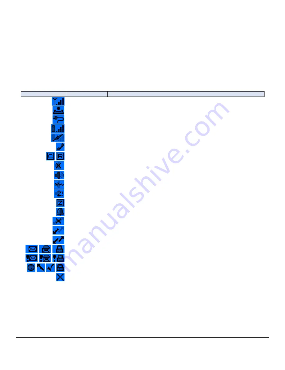
5.1


Icons 

Icon 

Name 

Meaning 


RSSI 

Display 0-4 bars indicating the control channel received signal strength 


Dock 

Indicates the pager is correctly inserted into a charging dock 


Cable 

Indicates the pager is correctly plugged into a charging cable 


Battery Level 

Displays 0-4 bars indicating the current capacity level of the battery. 


Battery Charge 

Indicates that the battery is currently charging 


Phone Message 

Indicates the presence of a new telephone message. 


Campus / 
Roaming  

Indicates that the pager is in campus or roaming coverage. 


Silent Mode 

Indicates that the pager is in silent mode. 


Normal Alert 
Mode 

Indicates that the pager is in normal alert mode. 


Vibrate Mode 

Indicates that the pager is in vibrate mode. 


Stealth Mode 

Indicates that the pager is in stealth mode. 


Quiet Time 

Indicates that the pager is set for quiet time. 


Alarm 

Indicates an alarm is set. 


No Coverage 

Indicates that the pager currently has no control channel. 


1-way Coverage 

Indicates that the pager has a control channel, but has not yet registered 
with the system. 


2-way Coverage 

Indicates that the pager is registered with the system. 


Message 

Represents an unopened, opened, or locked message. 


Priority Message 

Represents an unopened, opened, or locked priority message. 


Transmit 
Message 

Represents a queued, sending, sent, or locked transmit message. 


Failed Message 

Represents a message transmission that has failed. 


Summary of Contents for M1503 Responder II

Page 1: ...ument 12 077 Version 1 3 Critical Response System Inc 1670 Oakbrook Drive Suite 370 Norcross GA 30093 1849 Tel 770 441 9559 www criticalresponse com Copyright 2005 2013 Critical Response Systems Inc A...

Page 2: ...hts Reserved 2 Document Information RESPONDER and SPARKGAP are trademarks of Critical Response Systems Inc FLEX and ReFLEX are trademarks of Motorola For More Information please contact Critical Respo...

Page 3: ...our M1503 8 1 2 Engaging the Battery 8 1 3 Turning the Pager On 8 2 M1503 Response Pager 9 2 1 LCD Display 9 2 2 Buttons 9 2 3 User Interface 9 2 4 Status LED 10 2 4 1 Receiver Operation 10 2 4 2 Mess...

Page 4: ...Messages 19 5 8 Setup 20 5 8 1 User Status 21 5 8 2 Pager Settings 21 5 8 2 1 Quiet Time 21 5 8 2 2 Alert Mode 21 5 8 2 3 Optimize 22 5 8 2 4 Message Font 22 5 8 2 5 Status LED 22 5 8 2 6 Reminder Act...

Page 5: ...ical Response Systems Inc All Rights Reserved 5 5 8 4 6 Snooze Interval 27 5 8 4 7 Bedside Mode 27 5 8 4 8 Alarm 1 Alarm 2 27 5 8 5 Pager Info 28 5 8 6 Pager Status 29 5 8 7 Shut Down 29 6 Care and Pr...

Page 6: ...gy The M1503 transmits in the frequency range of 896 902 MHz and employs digital modulation techniques The M1503 output power level is typically 1 Watt In 1991 the Institute of Electrical and Electron...

Page 7: ...heres Do not charge your batteries or operate your battery charger within the proximity of any potentially explosive atmospheres It is rare but these actions may generate sparks Areas with a potential...

Page 8: ...s disconnected prior to shipment using a small battery disconnect switch located next to the data connector under a protective dust cover Prior to operating your pager you must engage the battery by s...

Page 9: ...ncludes four buttons Up Down Escape and Select 2 3 User Interface The M1503 user interface consists of a hierarchical menu system displayed on the LCD and navigated with the four buttons Up Down Selec...

Page 10: ...will snap into place where it will be held firmly during normal use To remove the pager from the holster simply grasp the pager and slide it up and out When using the translucent holster the pager can...

Page 11: ...then connect the other end of the cable to the wall adapter or computer 3 1 Dock LEDs During the charging process two LEDs on the basic dock display the charging status of the pager battery using a g...

Page 12: ...igating into the relevant folders you can review previously received messages Your system administrator can assign email addresses and phone numbers to each folder in your M1503 depending on relevant...

Page 13: ...cating the control channel received signal strength Dock Indicates the pager is correctly inserted into a charging dock Cable Indicates the pager is correctly plugged into a charging cable Battery Lev...

Page 14: ...e bottom and the current time and date at the top You can use the up down button to select one of the following choices Field Description Received Messages This menu item allows you to view and manage...

Page 15: ...ng the folder you want to examine You may open the message for viewing or other actions by selecting the particular message of interest Your M1503 can store a maximum of 200 total messages across all...

Page 16: ...specified by the message sender Folder Advanced This field displays the folder containing the message Queue Basic This field contains the time and date the message was sent into the system This heade...

Page 17: ...sending a reply by pressing Escape button Depending on the message the responses shown in the list may include preprogrammed responses as well as embedded responses Preprogrammed responses are loaded...

Page 18: ...as both a transmission queue and archival storage 5 6 1 Message Options You may press the Select button while viewing a message to open the message options pop up menu This pop up menu enables to tak...

Page 19: ...ks depending on your agency or department procedures and circumstance Your M1503 supports up to 32 canned messages and 15 canned addresses To send a message from your M1503 select the Send a Message m...

Page 20: ...e User Status pop up enabling you to change your current user status Pager Settings Opens the Pager Settings page enabling you to view and modify parameters related to general pager operation Folder S...

Page 21: ...Settings page 5 8 2 1 Quiet Time The Quiet Time parameter allows you to put your M1503 in a mode where alerts and reminders can be silenced on a folder by folder basis for non priority messages Settin...

Page 22: ...2 6 Reminder Action The Reminder Action parameter defines whether and how your pager reminds you about unread messages either Off Vibrate Low Medium or High The Off value disables the reminder functio...

Page 23: ...sound each time you press a button When set to No button presses will not make any sound 5 8 2 14 Charging LED The Charging LED parameter determines whether LEDs on the basic dock 3 indicate charging...

Page 24: ...page contains 3 settings or 2 for the global folder plus sub pages for folder normal and priority alert settings 5 8 3 1 1 Settings The Settings parameter determine whether the folder uses the Global...

Page 25: ...The Melody parameter specifies the melody played by the M1503 speaker upon receipt of a non priority message 5 8 3 2 2 Volume The Volume parameter specifies the loudness of the melody played upon rece...

Page 26: ...ty Alert Settings page allows you to specify the behavior of a folder as it receives priority messages You may navigate and set these parameters to customize the detailed behavior of each folder 5 8 3...

Page 27: ...nly if you set the TZ Source parameter to User 5 8 4 5 User DST The User DST parameter allows you to specify whether your pager observes daylight savings time either Standard or Daylight The pager obs...

Page 28: ...4 8 4 Volume The Volume parameter specifies how loud to play the melody when the alarm goes off either Off Low Medium or High 5 8 4 8 5 Dock Volume The Dock Volume parameter specifies how loud to play...

Page 29: ...r Status screen shows the current status of the pager including system information signal strength battery condition and other information Please contact your system administrator for the meaning and...

Page 30: ...itry and components 6 2 Use of Holster and Lanyard Excessive drops may damage or reduce the performance of your pager and should be avoided Use of the holster and lanyard will help prevent accidental...

Reviews: