background image

Software Crestron 

Serial Mouse Control Driver 


NOTE:

  Certain pairs of COM ports, such as 1 and 3, or 2 and 4, may be configured to use 

the same system interrupts within the Windows operating system, making it difficult to use 
both COM ports simultaneously. If so, it may be necessary to change the COM port setting. It 
is strongly recommended that the selected COM port be dedicated only for the Serial Mouse 
Control Driver. Refer to the Windows documentation for further information. 

NOTE:

  Crestron recommends that the baud rate for both the touchpanel and PC port be set 

at the default rate of 

9600

N, 8, 1

Open the UPDD Driver


folder and run 

setup.exe

. All of the default settings should be kept, 

although two may be altered if desired. For example, the name of the pointer device can be 
changed from the default "Device 1" to "Crestron Touchpanel". In the Port dialog, a COM 
port other than the default COM1 can be selected, to specify the COM port from which the 
PC will receive the serial mouse commands.  

Setup.exe will finish with a prompt to restart the computer. The computer 

MUST

 be 

restarted. After restarting the computer, open the UPDD Playback Utility folder and run 

setupply.exe

. The default settings should not be altered. Navigate through each dialog and 

accept each default to complete the installation. 

The Windows 

Start

 menu will now list UPDD and UPDD Playback Utility as programs, and 

the system tray of the Windows status bar will include icons shown below.  

Pointer Device Settings & Event Scheduler Icons  


After the system has been configured and programmed as outlined in the rest of this guide, it 
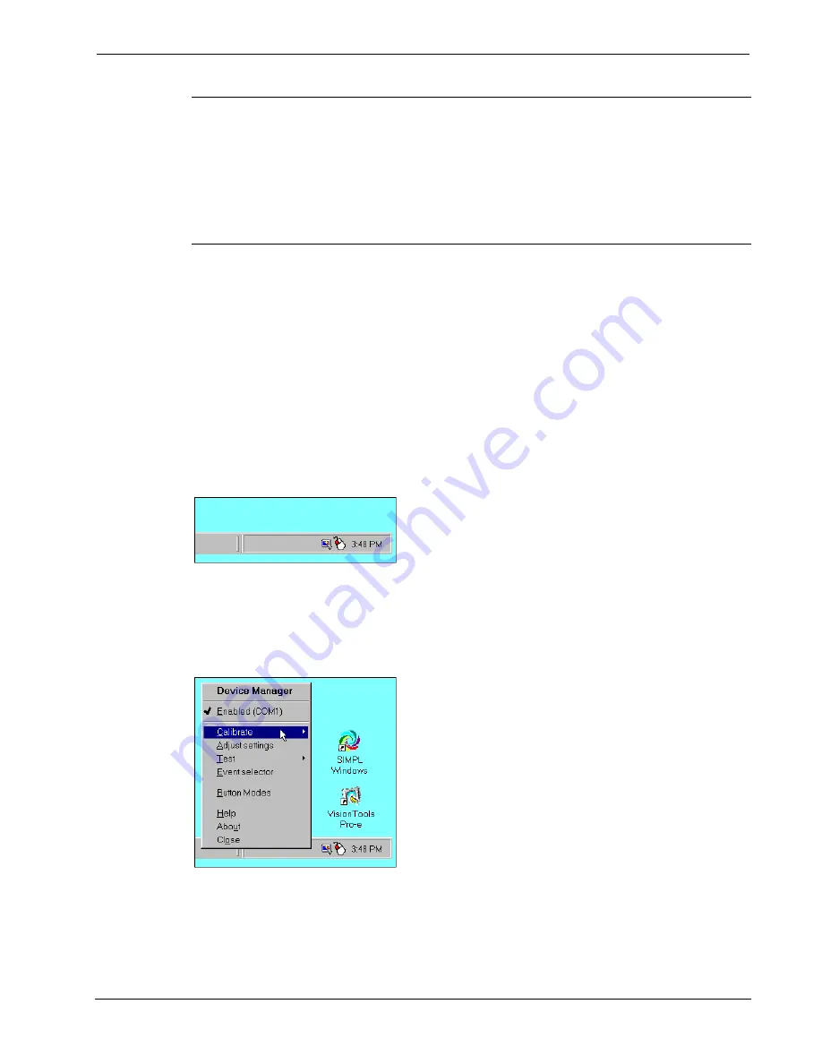
can be calibrated (or tested). Right-click the Pointer Device Settings icon and as shown 
below, select 

Calibrate

 from the Device Manager menu. Select 

Device 1 | Normal

 and 

calibrate the screen by following the onscreen directions. 

Select Calibrate  


The COM port can be changed by selecting 

Adjust settings

 from the Device Manager menu. 

As shown below, open the 

Hardware

 tab and choose a COM port from the drop-down list.  

4  

  Serial Mouse Control Driver 

Programmer’s Guide - DOC. 5916A 

Summary of Contents for Serial Mouse Control Driver

Page 1: ......

Page 2: ...This document was prepared and written by the Technical Documentation department at Crestron Electronics Inc 15 Volvo Drive Rockleigh NJ 07647 1 888 CRESTRON...

Page 3: ...Programming 16 Problem Solving 19 Troubleshooting 19 Further Inquiries 22 Future Updates 22 Future Firmware Upgrades 22 Appendix 1 Keyboard Functionality 23 Appendix 2 Additional PC and Mouse Function...

Page 4: ......

Page 5: ...sor to a location with the Mouse Driver and then move it to a different location with the regular mouse the Serial Mouse Driver thinks it is still at the earlier location Before you can perform a func...

Page 6: ...ds page TOUCHPNL and UPGRADES Libraries of Crestron s website Crestron recommends that the latest firmware be loaded into the touchpanel 4 The PC requirements pertain only to the Serial Mouse Control...

Page 7: ...ro e page 16 Set the RGB object to PAD 1 or PAD 2 Set the project properties according to the RGB selected PAD area Type Mouse Communication via TCP IP Serial Join 1 example Device ID 3 example Save C...

Page 8: ...from which the PC will receive the serial mouse commands Setup exe will finish with a prompt to restart the computer The computer MUST be restarted After restarting the computer open the UPDD Playbac...

Page 9: ...ght pages PC to Touchpanel Serial Communication For Serial Mouse Control Driver operation using serial communication from the PC to the touchpanel refer to the steps below 1 At the touchpanel enter th...

Page 10: ...NET Z G 2 4V DC Y 2 4 2 0A V IDEO BALANCED RGB Y COM P C CRESTRON TP S I MC BV RS 232 PORT COM PORT COMM CABLE VGA PORT A B C NET OR CRESNET PORT CRESNET WIRING NET PORT NET VIDEO PORT E TO NET VIDEO...

Page 11: ...ity and operating power For Cresnet 4 wire specifications refer to Appendix 3 on page 25 of this guide A standard stranded VGA monitor cable with DB15F to BNC 5 adapter is required Both are commercial...

Page 12: ...O INPUT AUDIO R S L S C O AX MIC OUT S NT SC PAL VIDEO NET Z G 2 4VDC Y 2 4 2 0A VIDEO B AL ANC ED RGB Y C OMP C CRESTRON TP S I M C B V COM PORT VGA PORT NET OR CRESNET PORT A C COMM CABLE B D E BKLT...

Page 13: ...ct the LAN port on the control system and the LAN port on the touchpanel base directly instead of through an Ethernet hub use an Ethernet crossover cable not supplied NOTE A Crestron TPS ENET or TPS E...

Page 14: ...5 8 pin Touchpanel LAN E 4 na na Touchpanel 24VDC 2A 1 2 3 4 REF ETHERNET COMMUNICATION 1 TILT TOUCHPANEL WITH TPS XVGA CARD CABLING REQUIRED TO Control System DEVICE PC Standard Ethernet cables ref C...

Page 15: ...PROCESSOR PRO2 CRESTRON PORT CONNECTOR to CONNECTOR DEVICE PORT A 1 VGA DB 15 male BNC 5 male Touchpanel RGB B 2 COM DB 9 female DB 9 female Control System COM C 3 NET 4 wire Cresnet 4 wire Cresnet To...

Page 16: ...ER command to add a CIP node to the master list of the touchpanel enter the information in the following format with spaces no period or underscore between the entries CIP ID from SIMPL Windows exampl...

Page 17: ...guration Manager add the appropriate Plug in Control Card or DPA Module to the control system and drag in the Cresnet or Ethernet enabled touchpanel The entries in the IP Table for IP ID and IP Addres...

Page 18: ...s shown below type or drag the specified string name to the tx input As shown Port A was selected Detail View of Serial Signals for the RS 232 COM Port in SIMPL Windows Programming Manager 3 In the SI...

Page 19: ...of the RS 232 COM Port in SIMPL Windows Configuration Manager 4 Compile and upload the SIMPL Windows program to the control system 5 Proceed to VT Pro e Programming that begins below on the next page...

Page 20: ...il in this section An RGB object must be created on a page or subpage To create an RGB object perform the following steps 1 In VT Pro e open the touchpanel project 2 As shown below make sure that the...

Page 21: ...tep 1 of SIMPL Windows Programming that begins on page 13 to reference the assigned touchpanel serial output from the Serial Join drop down list Then select the desired device ID from the Device ID dr...

Page 22: ...r s Guide Doc 5929 This document can be obtained from the What s New page Touchpanels section or Downloads page MANUAL and TOUCHPNL Libraries of Crestron s website www crestron com Search for TELE PDF...

Page 23: ...and use the touch output format command toformat to verify mouse control type toformat mouse and press ENTER Verify the setting type toformat and press ENTER This should display Current Touchout Form...

Page 24: ...todest and press ENTER This should display Current Touchout Destination Cresnet for Cresnet or Current Touchout Destination Ethernet for Ethernet communication PC serial port errors 1 Double click the...

Page 25: ...ialog box Select Buttons tab and adjust double click speed CAUTION Continued PC serial port errors The next troubleshooting action should be performed ONLY by advanced PC users If performed incorrectl...

Page 26: ...ew features and extends the capabilities of the Serial Mouse Control Driver additional information may be made available as manual updates These updates are solely electronic and serve as intermediary...

Page 27: ...r in various ways In particular there are four bits labeled EV00 EV01 EV02 EV03 that are interpreted as actions and not mouse positioning Select a trigger name and then EV00 through EV03 respectively...

Page 28: ...5B Sys Touchout Action 6 Touchout Action 6B Sys Touchout Action 7 Touchout Action 7B Sys Touchout Action 8 Touchout Action 8B Sys Touchout Action 9 Touchout Action 9B Sys Touchout Action A Touchout A...

Page 29: ...r of the run should be used in the resistance equation below to calculate the value on the right side of the equation Resistance Equation R Resistance refer to next table L Length of run or chain in f...

Page 30: ...optional lengths Part number TPS CBL T3 is the 3 foot version TPS CBL T6 is a 6 foot version and TPS CBL T9 is the 9 foot version This cable may be used for any system configuration when NET VIDEO RGB...

Page 31: ...rcially available RJ11 Modular Cable Pinouts PIN DESCRIPTION PIN DESCRIPTION 1 CTS Clear to Send 4 TxD Transmitted Data 2 GND 5 RTS Request to Send 3 RxD Received Data 6 Not Connected PC to Touchpanel...

Page 32: ...ommands data or instructions from or to another computer b for local campus or wide area network internet or web hosting services or c pursuant to any rental sharing or service bureau arrangement The...

Page 33: ...f ninety 90 days from the date of receipt and b that any hardware accompanying the Software will be subject to its own limited warranty as stated in its accompanying written material Crestron shall at...

Page 34: ...covered This warranty extends to products purchased directly from CRESTRON or an authorized CRESTRON dealer Purchasers should inquire of the dealer regarding the nature and extent of the dealer s warr...

Page 35: ...Crestron Serial Mouse Control Driver Software This page intentionally left blank Programmer s Guide DOC 5916A Serial Mouse Control Driver 31...

Page 36: ...Crestron Electronics Inc Programmer s Guide DOC 5916A 15 Volvo Drive Rockleigh NJ 07647 02 02 Tel 888 CRESTRON Fax 201 767 7576 Specifications subject to www crestron com change without notice...

Reviews: