30
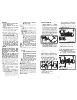
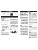
FRONT WHEEL TOE-IN/CAM BER
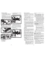
Your new tractor front wheel toe-in and
camber is set at the factory and is normal.
The front wheel toe-in and camber are not
adjustable. If damage has occurred to
affect the factory set front wheel toe-in or
camber, contact a Sears or other qualified
service center.
0066
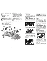
3
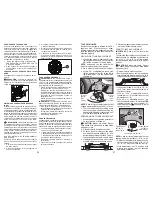
Retaining
Ring
Washers
Square
Key
(Rear Wheel Only)
Axle
Cover
Weak or
Dead
Battery
Fully
Charged
Battery
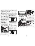
TO START ENGINE WITH WEAK BAT TERY
WARNING:
Lead-acid batteries gen er-
ate ex plo sive gases. Keep sparks, flame
and smoking ma te ri als away from bat ter ies.
Always wear eye pro tec tion when around
batteries.
If your battery is too weak to start the engine, it
should be recharged. (See "BATTERY" in the
MAINTENANCE section of this man u al).
If “jumper ca bles” are used for emer gen cy
starting, follow this pro ce dure:
IMPORTANT
: Your tractor is equipped with
a 12 volt system. The other vehicle must also
be a 12 volt system. Do not use your tractor
battery to start other vehicles.
TO ATTACH JUMPER CABLES -
1. Connect one end of the RED cable to the
POSITIVE (+) terminal of each battery(A-
B), taking care not to short against tractor
chassis.
2. Connect one end of the BLACK ca ble
to the NEGA TIVE (-) terminal (C) of fully
charged battery.
3. Connect the other end of the BLACK
cable (D) to good chassis ground, away
from fuel tank and bat tery.
TO REMOVE CABLES, REVERSE ORDER -
1. BLACK cable first from chassis and then
from the fully charged battery.
2. RED cable last from both batteries.
02239
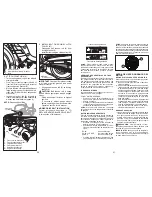
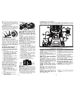
Adjustment Bolt
Neutral
Lock Gate
Motion Control
Lever
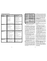
TRANSAXLE MOTION CON TROL LE-
VER NEUTRAL AD JUST MENT
The motion control lever has been pre set
at the factory and adjustment should not
be necessary.
1. Loosen adjustment bolt in front of the
right rear wheel, and lightly tight en.
2. Start engine and move motion con-
trol lever until tractor does not move
forward or backward.
3.
Hold motion control lever in that posi-
tion and turn engine off.
4. While holding motion control lever in
place, loosen the adjustment bolt.
5. Move motion control lever to the neu-
tral (N) (lock gate) position.
6. Tighten adjustment bolt securely.
NOTE:
If additional clearance is needed
to get to ad just ment bolt, move mower
deck height to the lowest position.
After above adjustment is made, if the
tractor still creeps forward or backward
while motion control lever is in neutral
position, follow these steps:
1. Loosen the adjustment bolt.
2. Move the motion control lever 1/4 to
1/2 inch in the direction it is trying to
creep.
3. Tighten adjustment bolt securely.
4. Start engine and test.
5. If tractor still creeps, repeat above
steps until satisfied.
REPLACING BATTERY
WARNING:
Do not short bat tery ter mi nals
by al low ing a wrench or any other object to
contact both terminals at the same time.
Before con nect ing battery, remove metal
bracelets, wrist watch bands, rings, etc.
Positive terminal must be connected first to
prevent spark ing from ac ci den tal grounding.
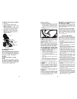
1. Lift seat pan to raised position.
NOTE:
On rear wheels only: align grooves in
rear wheel hub and axle. Insert square key.
4. Replace washers and snap retaining ring
securely in axle groove.
5. Replace axle cover.
NOTE:
To seal tire punctures and pre vent
flat tires due to slow leaks, purchase and
use tire sealant from Sears. Tire sealant also
pre vents tire dry rot and corrosion.
47
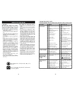
Nuestros tractores cumplen con los estándares de seguridad del
American National Standard Institute.
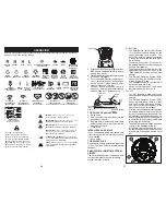
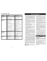
(A) PALANCA DEL LEVANTAMIENTO DEL AC-
CESORIO
- Se usa para levantar, bajar y ajustar
el conjunto segador o los demás ac ce so rios
montados en su tractor.
(B) PEDAL DEL EMBRAGUE/FRENO
- Se usa
para desembragar y frenar el tractor y para hacer
arrancar el motor.
(C) PALANCA DEL FRENO DE ESTACIONA-
MIENTO
- Ase gu ra el pedal del embrague/freno
en la posición del freno.
(CC) SÍMBOLO DE FRENO DE ESTACIONA-
MIENTO
- Indica una falla de arranque cuando
el freno de estacionamiento está desconectado.
(D) CONTROL DE ACELERACIÓN -
Se usa para
controlar la velocidad del motor.
(E) INTERRUPTOR DEL EMBRAGUE DEL AC-
CESORIO -
Se usa para enganchar las cuchillas
segadoras o los demás ac ce so rios montados en
su tractor.
(EE) SÍMBOLO DE INTERRUPTOR DE
CUCHILLAS
- Indica una falla de arranque
cuando el interruptor del embrague del accesorio
está activado.
( F ) B O T Ó N D E L I N T E R R U P T O R D E
ARRANQUE S
MART
S
WITCH
(SSI)
- Se usa
para arrancar/detener el motor y comunicar las
actualizaciones de estado.
(G)* SISTEMA DE FUNCIONAMIENTO EN
REVERSA (ROS)
- Permite la operación de
la plataforma de la cortadora de césped o de
otro accesorio eléctrico mientras se conduce
en reversa.
(H)* BOTÓN DE FAROS DELANTEROS
-
Enciende y apaga los faros delanteros.
(I)* BOTÓN INDICADOR DE LA BATERÍA
- Se
utiliza para indicar el voltaje bajo de la batería o
una falla del sistema de carga.
(J) PALANCA DE CONTROL DE MOVIMIENTO -
Selecciona la velocidad y la dirección del tractor.
(M) CONTROL DE RUEDA LIBRE
- Desengan-
cha la trans-misión para empujar o arrastrar.
(P) DISPOSITIVO DE AVISO DE SERVICIO/
CRONÓMETRO -
Indica cuándo hay que hacer-
les el servicio al motor y a la cortadora.
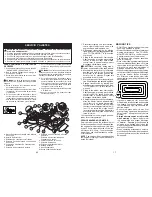
FAMILIARICESE CON SU TRACTOR
LEA ESTE MANUAL DEL Y LAS REGLAS DE SEGURIDAD ANTES DE OPERAR SU TRACTOR
Compare las ilustraciones con su tractor para familiarizarse con las ubicaciones de los diversos
controles y ajustes. Guarde este manual para referencia en el futuro.
E
A
B
C
J
CC
EE
I
G
D
M
F
H
P
* AVISO: "
G", "H" e "I" se utilizan como botones
de introducción numérica para escribir la
contraseña.

