56
TRACTOR
Siempre observe las reglas de seguridad cuando
dé man te ni mien to.
OPERACIÓN DEL FRENO
Si el tractor necesita más de cinco (5) pies (1,5 m)
para detenerse a la máxima velocidad al cambio
más alto en una superficie nivelada, de hormigón o
pavimentada, hay que hacerle el servicio al freno.
Ver “PARA VERIFICAR SI FUNCIONA BIEN EL
FRENO” en el capítulo de Servicio y ajustes de
este manual.
LLANTAS
• Mantenga todos los neumáticos con la presión
de aire adecuada (Ver la PSI que se indica en
estos).
• Mantenga las llantas sin gasolina, aceite o
substancias químicas para control de insectos
que pueden dañar la goma.
• Evite los tocones, las piedras, las grietas pro-
fundas, los objetos afilados y otros peligros
que pueden dañar a las llantas.
AVISO:
Para arreglar las llantas perforadas
y péra prevenir que tenga llantas pinchadas a
causa de pequeñas fugas, puede comprar el
sello para llantas de su comerciante de partes de
repuesto más cercano. Elsello previene que las
llantas se sequen y también la corrosión.
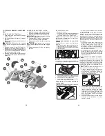
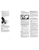
REMOCIÓN DE LA CUCHILLA
1. Levante la segadora a su posición más alta
para permitir el acceso a las cuchillas.
AVISO:
Proteja sus manos con guantes y/o
envuelva la cuchilla con una tela gruesa.
2. Remueva el perno de la cuchilla dandole
vueltas en el sentido inverso al de las agujas
del reloj.
3. Instale una hoja que sea nueva o se haya
vuelto a afilar, con el lado que tiene "GRASS
SIDE" grabado orientado al suelo.
IMPORTANTE:
Para asegurar la instalacion
apropiada, posicione el agujero central de la
cuchilla con la estrella del conjunto del mandril.
4. Instale y apriete el perno de la cuchilla firme-
mente (Par 45-55 Ft.-Lbs/62-75 Nm).
IMPORTANTE:
El perno especial de la cuchilla
es termotratado.
CUIDADO DE LA CUCHILLA
Para obtener resultados óptimos, las cuchillas
de la cortadora deben estar afiladas. Reemplace
las cuchillas que estén gastadas, dobladas o
dañadas.
BATERÍA
Su tractor cuenta con un sistema de carga de la
batería que es suficiente para el uso normal. Sin
embargo, si se carga la batería periódicamente,
con un cargador de automóviles, se prolongará
su duración.
• Mantenga la batería y los terminales limpios.
• Mantenga los pernos de la batería apretados.
• Mantenga los agu je ros de ventilación peque-
ños abiertos.
• Vuelva a cargar de 6-10 amperes por 1 hora.
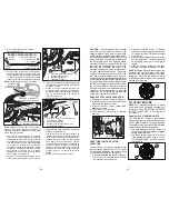
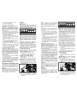
Conjunto del
Mandril
Cuchilla
Perno
de la
Cuchilla
Estrella
Agujero
Central
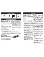
S I S T E M A D E P R E S E N C I A D E L
OPERADOR Y SISTEMA DE OPERACIÓN
EN REVERSA (ROS)
Asegúrese de que los sistemas de presencia del
operador y de operación en reversa funcionen de
manera correcta. Si su tractor no funciona conforme
se describe, repare el problema de inmediato.
• El motor no debe arrancar a menos que el
freno de estacionamiento esté activado y que
el control del embrague del accesorio esté en
la posición de desconexión.
REVISE EL SISTEMA DE PRESENCIA DEL
OPERADOR
• Cuando el motor está en marcha, se apaga
ante cualquier intento del operador de dejar el
asiento sin activar primero el freno de estac-
ionamiento.
• Con el motor en marcha y el freno de estac-
ionamiento y el embrague del accesorio ac-
cionados, el embrague del accesorio se apaga
ante cualquier intento del operador de dejar el
asiento.
• El embrague del accesorio nunca se debe
accionar si el operador no está situado en el
asiento.
REVISE EL SISTEMA DE OPERACIÓN EN
REVERSA (ROS)
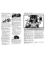
• Con el motor en funcionamiento, el botón (F)
del interruptor de arranque SmartSwitch (SSI)
en verde continuo y el embrague del accesorio
accionado, cualquier intento del operador de
cambio a reversa detiene las cuchillas de la
segadora.
F
G
• Con el motor en marcha, el botón (F) del
interruptor de arranque SmartSwitch (SSI) en
verde continuo y el botón ROS (G) iluminado,
cualquier intento del operador de cambio a
reversa detiene las cuchillas de la segadora.
21
02463
Closed
and
Locked
Position
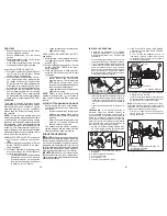
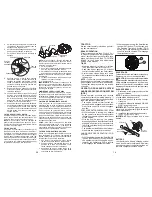
Oil Drain Valve
Yellow Cap
Drain
Tube
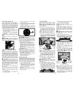
8. After oil has drained completely, close and
lock the drain valve by pushing inward
and turning clockwise until the pin is in
the locked position as shown.
9. Remove the drain tube and replace the cap
onto to the bottom fitting of the drain valve.
10. Refill engine with oil through oil fill dipstick
tube. Pour slowly. Do not overfill. For
approximate capacity see “PRODUCT
SPECIFICATIONS” section of this man u al.
11.Use gauge on oil fill cap/dipstick for check-
ing level. Ensure dipstick cap is tightened
securely for accurate reading. Keep oil at
“FULL” line on dipstick. Tighten cap onto
the tube securely when finished.
AIR FILTER
Your engine will not run properly using a
dirty air filter. Service paper cartridge every
100 hours of operation or every season,
whichever occurs first.
Service air cleaner more often under dusty
conditions.
NOTE
: If needed, remove lower dash covers
using steps from "Left Lower Dash Cover
Removal" section of this manual.
1. Remove cover.
2. Carefully remove air filter cartridge and
pre-cleaner from base.
3. Clean base carefully to prevent debris
from falling into carburetor.
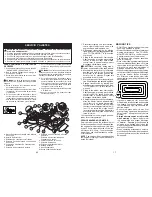
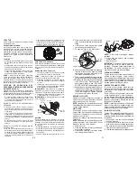
Pre-Cleaner
Knobs
Cover
Cartridge
NOTE
: If very dirty or damaged, replace
cartridge.
4. Place new pre-cleaner and cartridge
firmly in base.
5. Replace cover.
IMPORTANT:
Petroleum solvents, such as
kerosene, are not to be used to clean the
cartridge. They may cause de te ri o ra tion of
the cartridge. Do not oil cartridge. Do not
use pressurized air to clean cartridge.
IN-LINE FUEL FILTER
The fuel filter should be replaced once each
season. If fuel filter becomes clogged, ob-
struct ing fuel flow to car bu re tor, re place ment
is re quired.
1. With engine cool, remove filter and plug
fuel line sec tions.
2. Place new fuel filter in position in fuel line
with arrow pointing towards carburetor.
3. Be sure there are no fuel line leaks and
clamps are properly positioned.
4. Immediately wipe up any spilled gasoline.
CLEAN AIR SCREEN
The air screen is over the air intake blower
located on top of engine. The air screen
must be kept free of dirt and chaff to prevent
engine dam age from overheating. Clean with
a wire brush or compressed air to re move
dirt and stubborn dried gum fibers.
ENGINE OIL FILTER
Replace the engine oil filter every sea son or
every other oil change if the tractor is used
more than 100 hours in one year.
NOTE:
If needed, remove lower dash covers
using steps from "Lower dash cover removal"
section of this manual.
ENGINE COOLING SYSTEM
To ensure proper cooling, make sure the
grass screen, cooling fins, and other exter-
nal surfaces of the engine are kept clean
at all times.
Every 100 hours of operation (more often
under extremely dusty, dirty conditions),
remove the blower housing and other cooling
shrouds. Clean the cooling fins and external
surfaces as necessary. Ensure the cooling
shrouds are reinstalled.
NOTE
: Operating the engine with a blocked
grass screen, dirty or plugged cooling fins,
and/or cooling shrouds re moved will cause
engine damage due to overheating.
5. Remove yellow cap from end of drain
valve and install the drain tube onto the
fitting.
6. Unlock drain valve by pushing inward
and turning coun ter clock wise.
7. To open, pull out on the drain valve.

