62
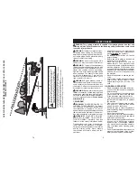
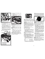
5. SI LA TIENE, INSTALE LA BARRA
ANTIBALANCEO (S)
Extremo Extremo
Con
En 90°
Arandela Integrada
BARRA ANTIBALANCEO (S)
Hacia El
Hacia La Plataforma
Transeje
De La Cortadora
De Césped
• Desde el lado derecho de la cortadora de
césped, inserte primero el extremo en 90° de la
barra antibalanceo (S) dentro del agujero de la
escuadra de transeje (T), ubicado cerca de la
rueda trasera izquierda adelante del transeje.
NOTA
: Puede resultar útil usar una linterna.
S
D
T
D. Escuadra Trasera Derecha De La
Cortadora De Césped
S. Barra Antibalanceo
T. Escuadra
Transeje
NOTA
: Dependiendo del modelo, la escuadra (T)
puede ser diferente de la que se ilustra, pero el
agujero para la barra antibalanceo estará en la
misma posición/ubicación.
• Haga oscilar el extremo con la arandela
integrada de la barra antibalanceo (S) hacia
la escuadra de la plataforma de la cortadora
de césped en el lado derecho de la cortadora.
Inserte el extremo con la arandela integrada
de la barra en el agujero de la escuadra
trasera de la cortadora de césped (D). Mueva
la cortadora de césped según sea necesario
para insertar el extremo con la arandela
integrada de la barra en la escuadra trasera
de la cortadora de césped (D).
• Asegure con una arandela pequeña y un res-
orte de retención pequeño, como se ilustra.
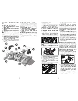
6. INSTALE LOS BRAZOS DE SUSPENSIÓN
LATERAL DE LA CORTADORA DE CÉSPED
(A) EN EL CHASIS
• Ubique el agujero delantero del brazo de
suspensión lateral (A) sobre la chaveta en la
parte exterior del chasis del tractor y asegure
con una arandela grande y un resorte de
retención grande (B).
• Repita en el lado opuesto del tractor.
B
D
A
A. Brazos De Suspensión Lateral De La
Cortadora De Césped
B. Resorte De Retención
D. Escuadra Tras-Era Derecha De La
Cortadora De Césped
7. INSTALE LOS ESLABONES DE LEVANTA-
MIENTO TRASEROS (C)
• Inserte el extremo de varilla del eslabón de
levantamiento trasero (C) dentro del agujero
(U) en el brazo de suspensión del eje de levan-
tamiento del tractor y haga oscilar el eslabón
hacia abajo hacia la cortadora de césped.
• Levante la esquina trasera de la cortadora de
césped y ubique la ranura en el conjunto de
eslabones sobre la chaveta en la escuadra
trasera de la cortadora (D); asegure con una
arandela grande y un resorte de retención
grande.
• Repita en el lado opuesto del tractor.
S
T
S. Barra Antibalanceo
T. Escuadra
Transeje
Ubicación
De La Barra
Antibalanceo (S)
Escuadra De Transeje (T)
Ubicada Entre Las Ruedas
Coloqu
e El Ex
tremo
En 90°
Coloque El Extremo En 90°
Dentro
Del Ag
ujero
Dentro Del Agujero
15
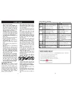
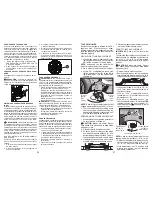
RESERVE FUEL VALVE OPERATION
1. Raise seat to access reserve fuel valve.
2. In normal operation, valve should be set
to primary (as shown in view)
3. If tractor runs out of fuel, rotate valve
handle to reserve.
4. Drive tractor to be refueled.
5. After refueling, return valve to primary
position.
Primary
Primary
Reserve
Reserve
Reserve
Reserve
Fuel Valve
Fuel Valve
F
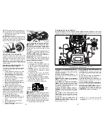
RESETTING IGNITION SYSTEM
PASSCODE
The S
MART
S
WITCH
Ignition is preset at the
factory with the default code "321". To reset
or change the passcode, the operator does
not have to be seated on the tractor.
1. Press the SmartSwitch Ignition (SSI) but-
ton (F) once (or sit on the seat). Ensure
the indicator is blinking blue.
TO START ENGINE
NOTE:
The default passcode "321" is preset
at the factory and should be changed prior
to first use. (See "RESETTING IGNITION
SYSTEM PASSCODE" in this section of
the manual.)
S
MART
S
WITCH
WARNING LIGHTS
The SmartSwitch Ignition is programmed
with warning lights to indicate when any part
of the safety system is not being followed.
The engine will not start until all the following
ignition system faults are resolved:
• The park brake symbol (CC) will be lit if
the parking brake has not been engaged
during a start attempt.
• The blade switch symbol (EE) will blink
if the attachment clutch control is not in
the "DISENGAGED" position during a
start attempt.
CAUTION:
Alcohol blended fuels (called
gasohol or using ethanol or methanol) can
attract moisture which leads to sep a ra tion
and for ma tion of acids during storage. Acidic
gas can damage the fuel system of an engine
while in storage. To avoid engine problems,
the fuel system should be emptied before
stor age of 30 days or longer. Drain the gas
tank, start the engine and let it run until the
fuel lines and carburetor are empty. Use
fresh fuel next season. See Storage In struc-
tions for additional information. Never use
engine or carburetor cleaner products in the
fuel tank or permanent damage may occur.
Fuel stabilizer is an acceptable alternative in
minimizing the formation of fuel gum deposits
during stor age. Add stabilizer to gasoline in
fuel tank or storage container. Always follow
the mix ratio found on stabilizer container.
Run engine at least 10 minutes after adding
stabilizer to allow the stabilizer to reach the
carburetor. Do not empty the gas tank and
carburetor if using fuel stabilizer.
2. Press and hold the (1) and (3) buttons
simultaneously for approximately three
(3) seconds until the SSI button changes
to solid blue.
3. Using the numbered buttons, enter the
desired passcode. The passcode may
be anywhere from one to five digits in
length.
4. After the desired passcode has been
entered, press the SSI button (F) once.
NOTE:
When the indicator flashes green, the
passcode has been accepted. If the indica-
tor blinks red, the passcode has not been
accepted. Wait until the indicator returns
to blinking blue and repeat this procedure
starting from step two.
CC
EE
F


