the lubrication hole in the bushing matches the oil
passage in the connecting rod.
WARNING
DO NOT MACHINE THE O.D. OR I.D. OF THE
BUSHING BEFORE PRESSING INTO
CONNECTING ROD.
4. If the holes in the wrist pin bushing and connecting
rod do not align, drill out the bushing through the
connecting rod lubricant passage with a long drill
bit. Bore the wrist pin bushing I.D. as indicated in
Appendix B, crosshead and connecting rod assembly
details. Over boring the bushing can lead to premature
failure of the wrist pin bushing.
5. Inspect the oil passage for debris and clean thoroughly
before proceeding.
6. Press the wrist pin back into the crosshead and wrist
pin bushing and reinstall retainer rings.
WARNING
The fit between the wrist pin and bushing
is tighter than lubricated air compressors
and combustion engines.
4.7.2 Replacing Connecting Rod Bearings
Connecting rod bearings are the semicircular bearings
in the large end of the connecting rods. Make sure
the indentations in the connecting rod bearing and
connecting rod line up when installing the new bearings.
KEEP CONNECTING RODS AND CAPS TOGETHER,
AND MAKE SURE THE ARROW AND/OR ALIGNMENT
NOTCH ON CONNECTING ROD AND CAP ARE ALIGNED.
Before reinstalling the crosshead/connecting rod
assembly, make sure the crankshaft throw and bearing
surface are clean and lubricated. Tighten the connecting
rod bolts to the torque values listed in Appendix B.
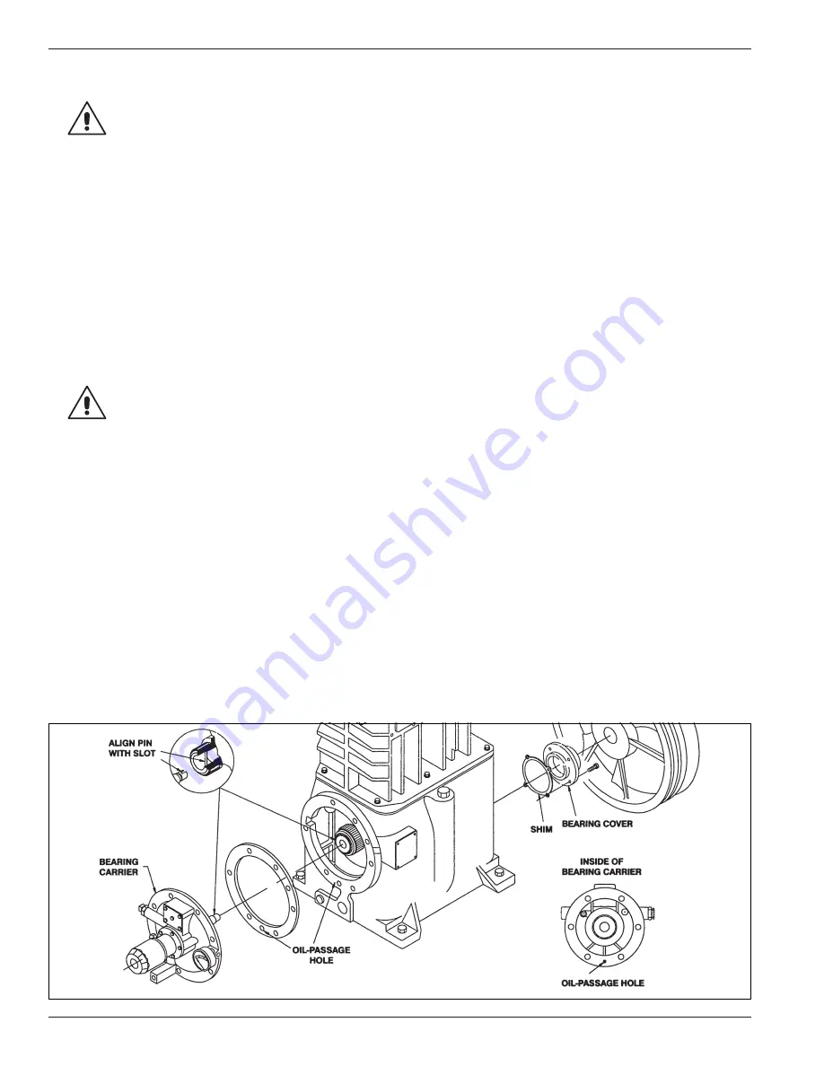
4.7.3 Replacing Crankcase Roller Main Bearings
To inspect the roller main bearings, remove the flywheel
from the crankshaft and then remove the bearing carrier
and crankshaft from the crankcase. If corrosion or
pitting is present, the roller bearings should be replaced.
When replacing roller bearings, always replace the entire
bearing and not just the cup or the cone.
1. To replace the bearings, press the cups out of the
crankcase and bearing carrier and press the cones off
the crankshaft.
2. Press the new bearings into position and reassemble
the crankshaft and bearing carrier to the crankcase.
When reinstalling the bearing carrier, make sure the oil
pump shaft slot is aligned with the pin in the crankshaft.
Make sure to install the bearing carrier gasket so the oil
passage hole is not blocked (see figure 4.7).
3. In order to check the crankshaft endplay, the oil pump
must first be removed (see section 4.8).
4. Press the end of crankshaft towards the crankcase; if
a clicking noise or motion is detected, the crankshaft
has too much endplay. For the proper amount of
endplay, see Appendix B.
5. To reduce endplay, remove the bearing cover and
remove a thin shim. Recheck the endplay after
replacing the bearing cover.
6. When there is no detectable endplay, the shaft must
still be able to rotate freely. If the crankshaft sticks
or becomes abnormally warm, then the crankshaft
bearings are too tight. If the crankshaft is too tight,
add more shims, but make sure not to over shim.
(Appendix B lists the proper crankshaft endplay). When
the crankshaft can be rotated freely by hand with
proper endplay, the rest of the compressor may be
reassembled. If the crankshaft roller bearings are too
tight or too loose, premature bearing failure will result.
7. Reinstall the oil pump and flywheel and check the run
out as shown in Appendix B.
Figure 4.7: Crankcase bearing replacement
18


