M O N T H L Y P R E V E N T I V E M A I N T E N A N C E P R O C E D U R E S
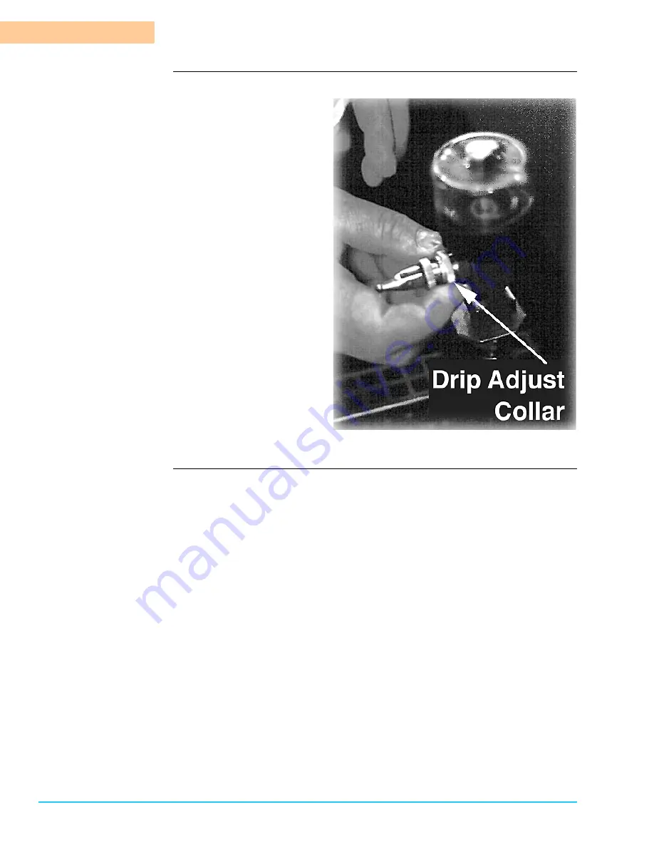
Pin Chain Conveyor (Option) Lubrication
5-50
Bravo™ 8105 Preventive Maintenance Guide
Rev. 2
5
Photograph
Figure 5–9
Page 1: ...Bravo 8105 CONVECTION REFLOW SYSTEM PREVENTIVE MAINTENANCE GUIDE Bravo 8105 Technical Manual P N 110 00 0 Bravo 8105 Preventive Maintenance Guide P N 3 9317 373 00 0...
Page 2: ...Bravo 8105 Preventive Maintenance Guide...
Page 3: ...00 0 Bravo 8105 Preventive Maintenance Guide i Preface Overview In this section This preface covers the following information Topic See Page To Our Customers ii Customer Support Structure iii Before Y...
Page 4: ...verview program development instructions standard operating instructions advanced operating instructions process troubleshooting scheduled maintenance overview and a list of error messages and audible...
Page 5: ...e Technologies Inc Electrovert Main Sales and Service Office Technical Service Support Group P O Box 709 Hwy 5 South Camdenton MO 65020 0709 Fax 573 346 6878 Tel 573 346 3341 or call Toll Free Tel 1 8...
Page 6: ...7 Phone 603 883 2488 South East Regional Service Center 1055 Windward Ridge Pkwy Suite 140 Alpharetta GA 30005 Fax 770 442 1987 Phone 770 619 5250 ext 16 North Central Regional Service Center 580 A To...
Page 7: ...rasse 1E 63303 Dreieich Germany Fax 49 6103 832 299 Phone 49 6103 832 0 Speedline Technologies Italy Via Liguria 2 28 I 20068 Peschiera Borromeo MI Italy Fax 39 2 5530 8468 Phone 39 2 5530 8339 Speedl...
Page 8: ...t support your machine in a timely fashion have the following specific information available when calling in System Software Version Serial Tag Information Machine Serial Tag The machine serial tag is...
Page 9: ...r Hazards 8 Heavy Objects 8 Skin Irritation 8 Section B Safety Precautions Recommended Precautions 9 Safety Lock Out Tag Out Procedures 9 No Smoking 9 Fire Extinguisher 9 Flammables 9 Electrical Preca...
Page 10: ...cations 23 Conveyor Specifications Table 24 Section C System Dimensions Physical Characteristics Table 25 Chapter 3 Preventive Maintenance Schedule Safety Reference 28 Section B Weekly PM Schedule Wee...
Page 11: ...Tools or Materials Necessary 51 Chapter 6 Quarterly Semi Annual and Annual Maintenance Preventive Main tenance Tables Mesh Belt Tension Adjustment 53 Section B Semi Annual Maintenance Electrical Conne...
Page 12: ...T A B L E O F C O NT E N T S x Bravo Preventive Maintenance Guide Rev 2...
Page 13: ...l safety and avoid equipment damage observe the following ATTENTION The information provided in the safety section of this document is not intended to supersede rules and regulations governing health...
Page 14: ...or may encounter while operating an Bravo System This section also describes warning tags installed on the system and ways to avoid the hazards encountered In this section Refer to the following hazar...
Page 15: ...zards and can cause severe skin burns The heat exposed surfaces of the system rails conveyor surfaces etc can become very hot Hot Surface Use extreme caution when working around or with hot components...
Page 16: ...res Keep flammable materials and solvents clear of the Bravo System Never stop the system with boards in the machine Flammable Motors Fire and Smoke Hazard Under normal circumstances motors tend to cr...
Page 17: ...re present on various parts of the system Safety To ensure personal safety and avoid equipment damage observe the following Electrical Hazard Installation of this equipment involves exposure to High V...
Page 18: ...king on or near moving parts and wear safety gear Safety To ensure personal safety and avoid equipment damage observe the following Entanglement Hazard All moving parts of the Bravo System represent p...
Page 19: ...fications Safety To ensure personal safety and avoid equipment damage observe the following Respirator All operators should be provided with an NIOSH or MSHA approved Respirator to provide effective p...
Page 20: ...y of these symptoms move to an area that is ventilated with fresh air immediately Compressed Gas Hazard Compressed Nitrogen Excessive pressure could cause explosion of Nitrogen Flow Meters Do not conn...
Page 21: ...attempting to move heavy equipment or components it is imperative to use the proper rigging equipment Do not attempt to move skids or large assemblies without the use of a fork lift or other rigging...
Page 22: ...rk area and provide measures for enforcement Fire Extinguisher Keep an approved fire extinguisher near the machine at all times Familiarized all personnel with the operation and use of the fire exting...
Page 23: ...els are measured at 914 4 mm 36 in height and distance from the front rear load and unload sides of the machine All noise levels consistently remain 70 dBa Safety Perimeter The machine is designed wit...
Page 24: ...National Standard Institute approved Safety Goggles NIOSH National Institute for Occupational Safety and Health OR MSHA Mine Safety and Health Administration approved Respirator Steel Toe Safety Shoes...
Page 25: ...t establish their own specific policies and procedures Safety To minimize system down time and ensure staff safety observe the following ATTENTION If procedures must continue past the shift of the per...
Page 26: ...horized electrician electrical engineer or service technician familiar with testing live voltage ATTENTION If procedures must continue past the shift of the person who applied the lockout device ensur...
Page 27: ...damage observe the following Electrical Hazard Electrical current used can kill DO NOT TOUCH live electrical components inside the electrical enclosure These procedures must be performed only by an a...
Page 28: ...procedures must be performed only by an authorized electrician electrical engineer or service technician familiar with testing live voltage Hot Surface Components in the system become hot during norma...
Page 29: ...tion upgrade or repair operations Safety To ensure personal safety and avoid equipment damage observe the following CAUTION If items removed during maintenance installation upgrade or repair procedure...
Page 30: ...S A F E TY IN F O R M A T IO N Remove Lock Out Tag Out Devices 1 18 Bravo 8105 Preventive Maintenance Guide Rev 2 1...
Page 31: ...This chapter provides the information the customer needs to prepare their facility for Bravo installation as well as operate the machine In this chapter This chapter consists of the following Topic S...
Page 32: ...oper exhaust ensures correct machine operation and safety Contact your local HVAC specialist for blower requirements and ventilation hook up Tables The following table identifies the facility requirem...
Page 33: ...C 3 phase 50 Hz 5 wires 3 phase 1 neutral 1 ground 440 480 VAC 3 phase 60 Hz 4 wires 3 phase 1 ground Start Up Power Requirements Table Refer to the following table for system start up power requireme...
Page 34: ...nal Electrical Code NEC ANSI NFPA 70 93 Electrical Standard for Industrial Machinery CE Compliance Declaration of Conformance is based on compliance to European Directives 89 392 EEC 91 368 EEC 93 44...
Page 35: ...on typical assemblies Heating Chamber Length 2667 mm 105 in Air Diffuser Panel Dimensions Length 254 mm 10 in Width 508 mm 20 in Heater Power Rating 4000 W per panel in zones 2 through 6 5000 W per pa...
Page 36: ...A T A Electrical Information 2 22 Bravo 8105 Preventive Maintenance Guide Rev 2 2 Forced Convection Air Cooling Module Table Cooling Chamber Length 762 mm 30 in Cooling Temperature Alarm Range 50 to...
Page 37: ...Right Conveyor Travel Conveyor Module Options Specifications Optional Features Alternate Right to Left Conveyor Travel Pin Chain Conveyor with Manual Width Adjust Pin Chain Conveyor with Computerized...
Page 38: ...in min Rail Parallelism 0 5 mm 0 020 in Process Width Mesh Belt 457 mm 18 in Pin Chain 50 mm to 432 mm 2 in to 17 in Process Height Mesh Belt 64 mm 2 5 in Pin Chain 32 mm 1 25 in Above 25 mm 1 0 in Be...
Page 39: ...m 194 5 in System Width 116 cm 46 0 in Height 145 cm 57 0 in Mesh Belt Conveyor Height 81 3 cm to 96 5 cm 32 0 in to 38 0 in Pin Chain Conveyor Height 83 8 cm to 99 1 cm 33 0 in to 39 0 in Access Clea...
Page 40: ...T E C H N IC A L D A T A Electrical Information 2 26 Bravo 8105 Preventive Maintenance Guide Rev 2 2...
Page 41: ...aning inspecting and servicing ensures consistent production quality and increases the extended service life of the machine The preventive maintenance tables are designed to enhance not replace any in...
Page 42: ...fety Information Safety Reference Introduction Operation of this equipment exposes personnel to potential health hazards Detailed information on safety hazards precautions and Lock Out Tag Out procedu...
Page 43: ...cedures within the hourly time guideline specific to the procedure PM Table Component Hours of Operation Procedure Photocell s 40 80 Clean the lens of the photocell s OPTION Pin Chain Conveyor Automat...
Page 44: ...inets Hood Fans 170 340 Vacuum the surface of the exhaust fans mounted in the hood Machine Exterior 170 340 Clean the exterior surface of the machine with an all purpose cleaner Main Gasket Seal 170 3...
Page 45: ...rocedure Quarterly Maintenance Table Semi Annual Maintenance Table Annual Maintenance Table Component Hours of Operation Procedure Mesh Belt Conveyor 525 Check the Mesh Belt to ensure that the tension...
Page 46: ...nd Annual Maintenance PM Tables 3 32 Bravo 8105 Preventive Maintenance Guide Rev 2 3 OPTION Pin Chain Conveyor 2100 Inspect chain tension and adjust if necessary OPTION Pin Chain Conveyor 2100 Inspect...
Page 47: ...inspect the minimum and maximum limit switches and the width linear transducer for damage or loose connections on a weekly basis approximately every 40 to 80 hours of operation Figure 4 1 Procedure T...
Page 48: ...attention to loose connections or screws on the switch mounting If necessary to replace use only Speedline Electrovert parts Analog Transducer Wire Inspection Introduction An analog transducer used fo...
Page 49: ...S Analog Transducer Wire Inspection 2 9317 373 00 0 Bravo 8105 Preventive Maintenance Guide 4 35 Photograph Figure 4 3 What to Look for Ensure that the transducer is mounted properly on the outside of...
Page 50: ...E E K L Y P R E V E N T IV E M A IN T E N A N CE P R O C E D U R E S Analog Transducer Wire Inspection 4 36 Bravo 8105 Preventive Maintenance Guide Rev 2 4 Photograph Figure 4 4 Ensure Solid Attachmen...
Page 51: ...nveyor on the Load End of the machine an optional exit photocell may be located at the conveyor exit point on the Unload End of the machine Tools or Materials Needed Non Abrasive Lint Free Cloth Anti...
Page 52: ...cooling zone Examine the heat exchanger to ensure that it is free of surface debris It is usually not necessary to clean the heat exchanger weekly but cleaning is dependent on process conditions If cl...
Page 53: ...avo 8105 one on the Load End and one on the Front center of the machine Clean the filters monthly approximately every 170 hours of operation Tools or Materials Needed Liquid All Purpose Cleaner Proced...
Page 54: ...M O N T H LY P R E V E N T IV E M A IN T E N A N C E P R O CE DU R E S Electrical Cabinet Filters 5 40 Bravo 8105 Preventive Maintenance Guide Rev 2 5 Photograph Figure 5 1 Photograph Figure 5 2...
Page 55: ...hly approximately every 170 hours of operation The fans are located on the inside of the top of the hood Electrical Hazard Ensure that power is removed from the machine before performing the following...
Page 56: ...on Clean the exterior surfaces of the Bravo 8105 monthly approximately every 170 hours of operation Tools or Materials Needed All Purpose Cleaner such as Formula 409 Non Abrasive Lint Free Cloth Proce...
Page 57: ...ide a tight seal for optimal reflow operation Inspect the seal monthly approximately every 170 hours of operation to ensure that the gasket provides a continuous seal Procedure Close the chamber on th...
Page 58: ...t is recommended to clean the Blowers monthly approximately every 170 hours of operation Electrical Hazard Remove power from the machine before performing the following procedure Electricity is presen...
Page 59: ...158 Procedure The Exhaust Plenums are located at the Load and Unload Ends of the machine They are the openings that draw the air into the exhaust system for the Bravo 8105 Refer to Figure 5 6 The Exh...
Page 60: ...Y P R E V E N T IV E M A IN T E N A N C E P R O CE DU R E S Exhaust Vent Cleaning 5 46 Bravo 8105 Preventive Maintenance Guide Rev 2 5 Photograph The arrow indicates the location of the Exhaust Plenum...
Page 61: ...ensure solid connections Tighten any connections that appear loose Lubrication of the pin chain conveyor is required after 160 hours of operation for most reflow operations Lubrication is required af...
Page 62: ...the oil only touches the chain and the chain tracks Photograph Figure 5 7 Automatic Oiler Operation 1 Load the oilers by lifting the oil fill cap at the top of the oiler reservoir and fill with 10cc o...
Page 63: ...M O N T H L Y P R E V E N TI V E M A I N TE N A NC E P R O C E D U R E S Pin Chain Conveyor Option Lubrication 2 9317 373 00 0 Bravo 8105 Preventive Maintenance Guide 5 49 Photograph Figure 5 8...
Page 64: ...M O N T H LY P R E V E N T IV E M A IN T E N A N C E P R O CE DU R E S Pin Chain Conveyor Option Lubrication 5 50 Bravo 8105 Preventive Maintenance Guide Rev 2 5 Photograph Figure 5 9...
Page 65: ...0 Cross Shaft Lubrication It is necessary to lubricate the cross shafts located on the Load End Unload End and in the center of the Bravo 8105 System Lubricate the shafts annually approximately every...
Page 66: ...he oven To access the center shaft it is necessary to remove the ten 10 screws with a 3 mm Allen wrench Refer to Figure 5 11 Clean the each of the width shafts with denatured alcohol to remove any acc...
Page 67: ...ure exposes maintenance personnel to dangerous voltage levels Do not touch live electrical components inside the machine Turn the Bravo 8105 System Off before performing this procedure Procedure Disco...
Page 68: ...duction resumed Procedure Cleaning the Heat Exchanger Clean the heat exchanger by submersing it in an appropriate solvent recommended by the flux manufacturer The heat exchanger needs to soak until th...
Page 69: ...east once a month Location of Limit Switches The limit switches are located in the Cooling Zone They are mounted on the top chamber section Both switches are located over the crosspiece that straddles...
Page 70: ...Location of Proximity Switches Two 2 proximity switches are located between the heating zones To access the proximity switches it is necessary to raise the heating zone hood of the machine The switch...
Page 71: ...Y P R E V E N TI V E M A I N TE N A NC E P R O C E D U R E S Limit Switches Pressure Switches and Proximity Switches Inspection 2 9317 373 00 0 Bravo 8105 Preventive Maintenance Guide 5 57 Photograph...
Page 72: ...hol or an appropriate flux solvent into the tray If a stan dard mesh belt conveyor is installed it is not necessary to remove it before spraying unless it is desired to wipe out the tray 3 Allow time...
Page 73: ...M O N T H L Y P R E V E N TI V E M A I N TE N A NC E P R O C E D U R E S Cooling Zone Tray Nitrogen Machine Option 2 9317 373 00 0 Bravo 8105 Preventive Maintenance Guide 5 59 Photograph Figure 5 17...
Page 74: ...e Rev 2 5 Cooling Zone Blower Cleaning Nitrogen Machine Option Introduction For optimal cooling performance keep the blowers in the Cooling Zone clean and free of debris Procedure Clean the blowers in...
Page 75: ...r process The belt is adjusted at the factory and needs adjustment only if it has slightly stretched due to process demands Inspect the belt quarterly approximately every 525 hours of operation Proced...
Page 76: ...e 6 1 N2 Option Entrance and Exit Curtains Inspection Description The Inert Bravo contains entrance and exit curtain modules designed to enclose the nitrogen environment The entrance curtains are trim...
Page 77: ...irst to see if any are noticeably loose or damaged There are electrical components in the electrical cabinet as well as on the rear of the chamber where the blowers are wired Check for any debris that...
Page 78: ...eed calibration annually also If the optional width adjust is installed with the optional pin chain conveyor verify on an annual basis that it is calibrated The blower and fan calibration is preset at...
Page 79: ...Med High Enter the new values into the Convection Hot column Lower Blower Cold and Hot Procedures Repeat the same procedure as performed on the Upper Blowers for each bank of blowers in the lower zone...
Page 80: ...ion and deceleration Rapid acceleration may cause the current limit circuit to activate This automatically extends the acceleration time Deceleration DEC The DEC trim potentiometer sets the time it ta...
Page 81: ...esh belt or rail to use as a reference spot Using a stop watch measure the time it takes for that point to travel a defined distance Use the following formula to calculate speed Speed Length Time When...
Page 82: ...lt with a 1 2 wrench Slide the Rail Guard off of the conveyor Operate the conveyor at low speed until the master link is located It is identifiable by an appearance that is different than the rest of...
Page 83: ...A L A N D A N N U A L M A IN T E N A N C E P R E V E N TI V E M A I N TE N A NC E T A B L E S Conveyor Tension Adjustment 2 9317 373 00 0 Bravo 8105 Preventive Maintenance Guide 6 61 Photograph Figur...
Page 84: ...Q U A R T E R L Y S E M I A N N U A L A N D A N N U A L M A IN T E N A N C E P R E V E N TI V E M A IN T E N A N C E T A B LE S 6 62 Bravo 8105 Preventive Maintenance Guide Rev 2 6...
Page 85: ...te FLA 21 Lock Out Tag Out 15 17 Requirements 21 Electrical Connections 65 Entrance and Exit Curtains 64 Exhaust Requirements 20 Ventilation 12 Exhaust Vent Cleaning 47 F Facility Exhaust Requirements...
Page 86: ...n 49 Pressure Switches 57 Preventive Maintenance Quarterly Semi Annual and Annual Maintenance 63 Protective Clothing 12 Proximity Switches 57 Q Quarterly Maintenance 63 Quarterly Semi Annual and Annua...
Page 87: ...2 9317 373 00 0 Bravo 8105 Preventive Maintenance Guide 3 IN D E X W Water Requirements 20 Weekly Maintenance 31 Weekly Preventive Maintenance 35...