36
Unidrive Regen Installation Guide
www.controltechniques.com
Issue Number: 2
Appendix B
Component sizing calculations
B.1
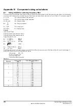
Sizing of MCB for switching frequency filter
The current rating of the MCB must be calculated; taking into account the switching frequency filter inductance and capacitance, the initial charging
current and the AC supply voltage. switching frequency filter inductance and capacitance values can be found in Chapter 5 Components on page 10.
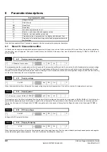
L = 2 x Lf
Lf = Switching frequency filter inductance
C = 3Cf / 2
Cf = Switching frequency filter capacitance
Vc = V
LL
peak
Vc = Charging voltage
Zc =
Zc = Charging impedance
Tc =
Tc = Charging time
Ic = Vc / Zc
Ic = Charging current
Example:
Unidrive size 5 Regen
Switching frequency filter Inductance 100
µ
H
Switching frequency filter Capacitance 80
µ
F
Supply Voltage 480v + 10%
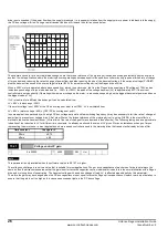
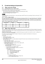
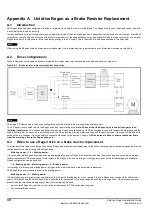
L =
2 x 100
µ
H =
200
µ
H
C =
3 x 80
µ
F / 2 =
120
µ
F
Vc =
480 + 10% x
√
2 =
747V pk
Zc =
=
1.29
Ω
Tc =
=
487
µ
s
Ic =
747 / 1.29 =
579A
The MCB should be rated to the peak charging current of 579A for 487
µ
s, with an rms current of 35A. Refer to Table 5-6 for a full list of ratings. A
suitable MCB should have the following ratings and features:
Voltage rating:
480 + 10%
Peak current rating: 579A
rms current rating: 35A
3 pole with auxiliary (for enable)
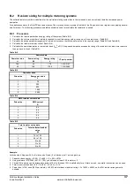
Table B-1
Drive size
Power rating
(kW)
Total DC bus capacitance
(
µ
F)
1
4.0
340
2
5.5
470
7.5
470
11.0
680
3
15.0
1,100
18.5
1,100
22.0
2,200
30.0
2,200
37.0
2,200
4
45
3,300
55
3,300
75
4,400
90
6,600
110
6,600
5
150
8,800
L
C
----
LC
π
200
µ
H
120
µ
F
------------------
200
µ
H
120
µ
F
×
π

