38
Unidrive Regen Installation Guide
www.controltechniques.com
Issue Number: 2
B.3
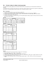
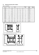
Multiple Unidrive size 5 systems
Table B-6
Resistors for Unidrive size 5 multiple systems
B.4
Thermal / magnetic overload protection for soft start circuit
Thermal / magnetic protection for the softstart resistor should be provided to protect against a high / low impedance short circuit and the risk of fire. A
recommended device being a thermal magnetic overload. The overload should be sized as following to provide thermal and magnetic protection:
B.4.1
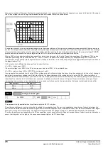
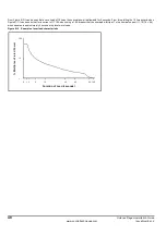
Thermal / magnetic overload characteristics
Figure B-1
Example of tripping characteristic
B.4.2
Sizing of magnetic overload
The magnetic overload should be selected to the peak current and charging time at power up with the trip being at for example 20 times the nominal
rated current of the overload. Therefore for a 20A peak current a 1A overload could be used.
The charging of a system takes a total of 5 time constants with this having a decaying exponential current due to the RC network, therefore at 5 time
constants the system will have charged up with the current being at approximately zero as shown in Figure B-2 on page 39.
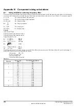
The peak current and charge time during power up can be calculated using the following formula.
Drive size
Number of parallel resistors
CT part number
5
Equal to total number of modules in the system (Regen and
motoring)
1270-2483
0.01
0.02
0.04
0.06
0.1
0.2
0.4
0.6
1
2
4
6
10
20
40
1
2
4
6
10
20
40
60
120
1.5
2
3
4
1
5
6
8
10
15
20
30
14
21
10
T
rippi
ng
time
S
e
c
o
nds
Mi
n
u
te
s
Multiple of rated current
Thermal Trip
Area
Hot
Cold
Magnetic Trip
Area


