Unidrive Regen Installation Guide
25
Issue Number: 2
www.controltechniques.com
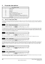
When the drive is enabled and the main contactor is closed it will try and synchronise the line supply. If this bit is 0 then the drive will continue to try
and synchronise to the line continually until disabled, even if it does not synchronise successfully. If this bit is set to a 1 and the drive has not
successfully synchronised after trying for 30 seconds then the drive will trip ‘LI.SYNC’.
This parameter is the line supply synchronisation status. It is intended to give some diagnostic information if the drive fails to synchronise to the
supply. If no attempt to synchronise to the supply has been made since the drive was switched on, if the drive is synchronised to the supply and
running, or if it has been running then this parameter will show ‘SYNC’. If the drive can not synchronise to the supply then this parameter will show the
reason why synchronisation failed. If the drive does fail to synchronise to the supply the most likely reasons are that the supply is very distorted, or
there are large voltage notches / spikes on the supply.
0
SYNC
Successfully synchronised to line supply
1
Ph Det
Failed to correctly detect the phasing of the supply
2
Fr Lo
Line frequency too low
3
Fr Hi
Line frequency too high
4
PLL OI
Over current during final synchronisation of PLL to supply
5
PLL Ph
Phasing error during final synchronisation of PLL to supply
N
These parameters are only available when the software version is 3.01.07 or higher
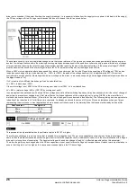
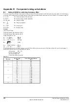
When the drive is operated as a Regen drive it uses a DC bus voltage controller with inner current controllers as shown below:
The gains of the voltage and current controllers affect the stability of the Regen drive control system and incorrect gain settings can result in over-
voltage or over-current trips. (The gain of the voltage controller is set by Pr 15.21). In most applications the default gains given for the current
conditions will be suitable, however, it may be necessary for the user to change these if the inductance or resistance of the supply plus the Regen
inductors varies significantly from the expected values.
The most critical parameter for stability is the current controller proportional gain and the required value for this is dependent on the Regen drive input
inductance. If the inductance of the supply is a significant proportion of the recommended Regen inductor (i.e. >60mH/I
DR
. where I
DR
is the drive
rated current), then the proportional gain may need to be increased. The supply inductance is likely to be negligible compared to the Regen inductor
value with small drives, but is likely to be significant with larger drives. The proportional gain should be adjusted so that
Pr 15.19 = 1800 x Total input L x I
DR
The current controller integral gain is not so critical, and in a majority of cases the default value is suitable. However, if it is necessary to adjust this
parameter a value between 80 x I
DR
x R and 320 x I
DR
x R (where R is the supply resistance of one phase) should be used.
Even when the gains are set correctly there will be a transient change of DC bus voltage when there is a change in the load on any drive connected
to the Regen drive. If the power flow from the supply is increased (i.e. more power is taken from the supply or less power is fed back into the supply)
the DC bus voltage will fall, but the minimum level will be limited to just below the peak rectified level of the supply provided the maximum rating of the
15.17
0.27
Line synchronisation trip enable
ô
0 ~ 1
ð
0
RO
Bit
15.18
0.28
Line synchronisation status
ô
0 ~ 5
ð
RO
Txt
P
15.19
Current control proportional gain
ô
0 to 30,000
ð
110
RW
Uni
15.20
Current control integral gain
ô
0 to 30,000
ð
1,000
RW
Uni
NOTE


