Unidrive Regen Installation Guide
29
Issue Number: 2
www.controltechniques.com
9.3
Regen drive commissioning
•
Ensure power and control connections are made as specified in this Installation Guide.
•
Ensure the Regen and motoring drives are not enabled.
•
Switch on the AC supply.
•
Both the Regen and motoring drives should now power up through the start-up circuit in standard open loop mode.
•
On the Regen drive, configure the drive type Pr 11.31 (Pr 0.48) to REGEN and set the additional parameters up for the auxiliary contactor (refer
to Chapter 4 Control circuit connections on page 8).
•
The Auxiliary and Main contactors should now close; the start-up circuit is disabled at this point.
•
On the Regen drive, set up the switching frequency and DC bus set point voltage to the required values in either Menu 0 or Menu 15, refer to
Chapter 8 Parameter descriptions on page 22. Save the parameters.
•
The Regen drive can now be enabled, the Regen drive should display ACT.
•
The commissioning of the motoring drive(s) can now be carried out.
9.4
Motoring drive commissioning
The setting of certain parameters in the motoring drive must be given special consideration when used in a Regen system.
Ramp Mode - Pr 2.04 (Pr 0.15)
When a motoring drive is used in a Regen system, the ramp mode should be set to FAST. The default setting of standard control will result in incorrect
operation.
Voltage Control Mode - Open loop only Pr 5.14 (Pr 0.07)
The default setting of UR_I does not function correctly in the motoring drive when used in a Regen system. When the system is powered up, the
motoring drive is disabled while the Regen synchronises to the AC supply. The resultant delay before the motoring drive is enabled means that the
stator resistance test cannot be completed. When open loop vector operation is required the voltage mode should be set to UR_S.
Drive Enable Function - Open loop only Pr 8.07
The default setting for terminal 30 in the open loop motoring drive is an external trip (Et) function. When the Regen drive has synchronised to the AC
supply and the enable signal is applied to the open loop drive, a drive reset is required to clear the external trip. If a reset signal is not available or
desirable, then Pr 8.09 should be set to a 1. Terminal 30 then acts as a non latching input with the drive displaying INH when disabled.
AC Supply Loss Mode - Pr 6.03
The motoring drive will not operate correctly if the AC supply loss mode is set to STOP. If the AC supply is lost, the Regen drive disables the motoring
drive and prevents a controlled stop from being completed.
Auto Start - Pr 6.02
The Auto Start function will not operate correctly when used in a Regen system due to the delay in applying the enable signal to the motoring drive as
described above in Voltage Control Mode. The delay means that the run latch has already cleared when the enable signal is applied.
9.5
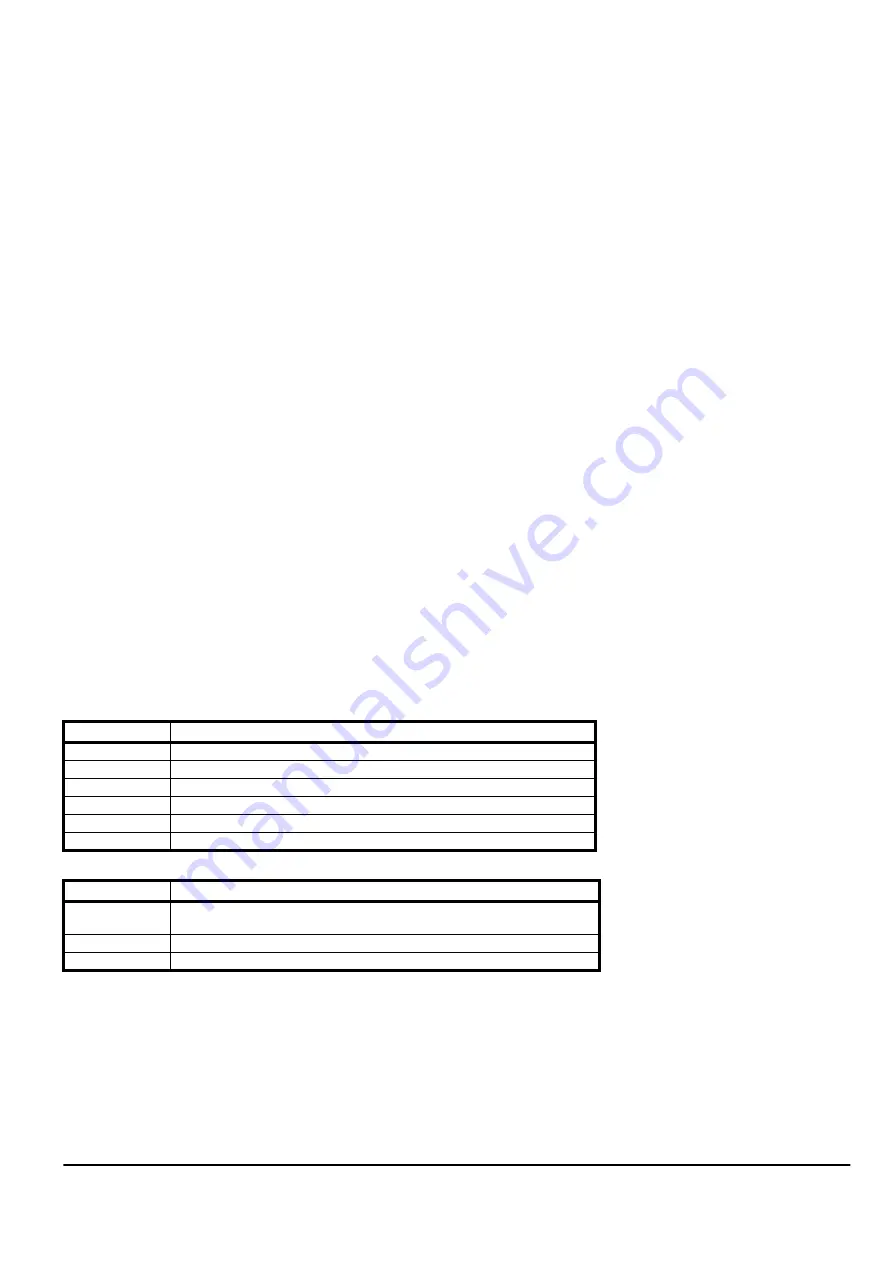
Trip codes
Below are the trip codes which are specific to Unidrive in Regen mode. These are in addition to the trips listed in the Unidrive size 1 to 5 User Guide.
Table 9-2
Trip codes
Table 9-3
Status display
Trip Code
Description
LI.SYNC
Regen sinusoidal rectifier failed to synchronise to line voltage
Ph Det
Failed to correctly detect the phasing of the supply
Fr Lo
Line frequency to low
Fr Hi
Line frequency to high
PLL OI
Overcurrent during final synchronisation of PLL to supply
PLL Ph
Phasing error during final synchronisation of PLL to supply
Status Display
Description
STOP
Drive Enabled but AC voltage too low, or DC bus voltage still rising, or DC bus
voltage still falling. Waiting for correct conditions to synchronise onto line
SCAN
Drive enabled and synchronising to line
ACT
Drive enabled, synchronised and active


