30
Unidrive Regen Installation Guide
www.controltechniques.com
Issue Number: 2
Appendix A
Unidrive Regen as a Brake Resistor Replacement
A.1
Introduction
The Regen drive has been designed to provide a regulated DC supply to other motoring drives. The Regen drive gives bi-directional power flow with
sinusoidal currents and a near unity.
In many applications, the motoring power can be significantly higher than the braking power. If sinusoidal input currents are not required, it is difficult
to justify the cost of a Regen drive rated at the full motoring power. In these applications it may be desirable to take the lower cost option of a smaller
Regen drive which is only used to return the braking energy to the AC supply. This is the mode of operation described in this Appendix.
N
When using the Regen drive as a brake resistor replacement, the information given in earlier sections of this guide must also be referred to.
A.2
Drive configurations
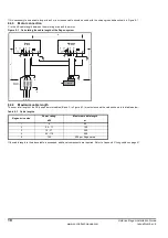
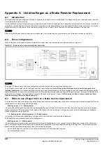
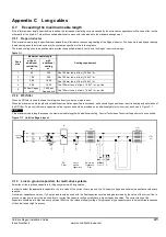
When a Regen drive is used as a dynamic brake resistor replacement, connections must be made as shown in Figure A-1.
Figure A-1
Brake resistor replacement system connection
N
The single RFI filter shown in the above configuration should be rated to the motoring drive’s rated current.
The AC supply is connected to both the Regen drive and the motoring drive. Note, however, that the Regen drive receives its supply via an
isolating transformer. This is necessary because when the Regen drive is switching, its DC bus voltage moves with respect to both ground and the
supply neutral point. However, on the motoring drive, the DC bus voltage remains relatively fixed with respect to ground. As a result of the difference
between the two voltages, it is not possible to connect both drives to the same AC supply. A DC bus diode is fitted to ensure that power flows
from the motoring drive to the Regen drive only.
A.3
When to use a Regen drive as a brake resistor replacement
The important factor when considering the use of a Regen as a brake-resistor replacement is the ratio of motoring power to braking power, as this has
implications for the power rating of the Regen drive.
Motoring power
≤
1.5
×
Braking power.
If the maximum motoring and braking power are approximately equal, a Regen drive should be used as the main supply and not solely as a brake-
resistor replacement. This is because, in this instance, the Regen drive and motoring drive ratings are equal, so the full advantage of a standard
Regen configuration can be exploited.
1.5
×
Braking power
<
Motoring power
≤
4
×
Braking power.
In this range of motoring and braking power, a Regen drive will work well as a brake-resistor replacement.
The Regen drive power rating is equal to the braking power.
Motoring power
>
4
×
Braking power.
If the motoring power is greater than approximately four times the braking power, it is not possible to use a Regen drive rated only for its braking
power. This is because the small Regen drive is unsuitable for connection to the large capacitance of the motoring drives. If the motoring power is
greater than four times the braking power, then the following can be used.
•
An over-rated Regen drive with a current rating at least equal to 0.25 x motoring drive power.
•
Conventional brake resistor.
NOTE
Regen Drive
fusing
Motoring
Drive fusing
NOTE

