


50
Unidrive M200/201 Control Quick Start Guide
Issue Number: 3
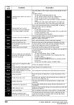
OI.AC
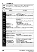
Instantaneous output over current
detected
The instantaneous drive output current has exceeded.The set
limit.
Possible solutions:
•
Increase acceleration/deceleration rate
•
If seen during autotune reduce the voltage boost
•
Check for short circuit on the output cabling
•
Check integrity of the motor insulation using an insulation
tester
•
Is the motor cable length within limits for the frame size
•
Reduce the values in the current loop gain parameters
OI.br
Braking IGBT over current
detected: short circuit protection
for the braking IGBT activated
Over current has been detected in braking IGBT or braking
IGBT protection has been activated.
Possible cause:
•
Check brake resistor wiring
•
Check braking resistor value is greater than or equal to the
minimum resistance value
•
Check braking resistor insulation
OI.Sn
Snubber over-current detected
This trip indicates that an over-current condition has been
detected in the rectifier snubbing circuit.
Refer to
Control User Guide
.
OI.SC
Output phase short-circuit
Over-current detected on drive output when enabled.
OPt.d
Option module does not
acknowledge during drive mode
changeover
Option module did not acknowledge notifying the drive that
communications with the drive has been stopped during the
drive mode changeover within the allocated time.
Out.P
Output phase loss detected
Phase loss has been detected at the drive output.
OV
DC bus voltage has exceeded the
peak level or maximum continuous
level for 15 seconds
The
OV
trip indicates that the DC bus voltage has exceeded the
maximum limit.
Possible solutions:
•
Increase
Deceleration Rate 1
(Pr
04
)
•
Decrease the braking resistor value (staying above the
minimum value)
•
Check nominal AC supply level
•
Check for supply disturbances which could cause the DC
bus to rise
•
Check motor insulation using a insulation tester
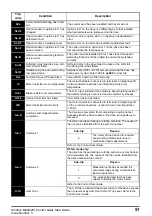
P.dAt
Power system configuration data
error
Contact the supplier of the drive.
Pb.bt
Power board is in bootloader mode Power board is in bootloader mode
Pb.Er
Communication has been lost /
errors detected between control &
power processor
Communications loss between control and power processor.
Pb.HF
Power board HF
Power processor hardware fault - contact the supplier of the
drive
Pd.S
Power down save error
Error has been detected in the power down save parameters
saved in non-volatile memory.
PH.Lo
Supply phase loss
The drive has detected an input phase loss or large supply
imbalance.
PSU
Internal power supply fault
One or more internal power supply rails are outside limits or
overloaded.
r.ALL
RAM allocation error
Option module derivative image has requested more parameter
RAM than is allowed.
r.b.ht
Hot rectifier/brake
Over-temperature detected on input rectifier or braking IGBT.
rS
Measured resistance has
exceeded the parameter range
The measured stator resistance during an autotune test has
exceeded the maximum possible value of
Stator Resistance
.
Refer to the
Control User Guide
.
Trip
code
Condition
Description


