Chapter
8
Hardware RAID setup
Chapter8
Hardware RAID setup
This chapter describes hardware mirroring (RAID1) setup. We only support mirroring. We
do not support operation for other RAIDs (RAID0, RAID5, and RAID10). Be aware that
functions not supported are outside the scope of the warranty.
Hardware RAIDs are also hot-swappable.
Functional specification
For more on the specifications of RAID boards (hereinafter described as “mirror card”)
used for hardware RAIDs, refer to Chapter 2 “General”- “Specification”.
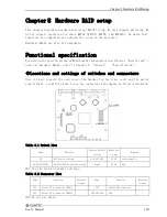
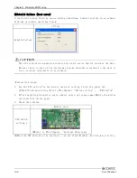
◆Locations and settings of switches and connectors
Once you have removed the case cover, the bracket for the riser card, and the mirror
card bracket, you will be able to see the connectors and jumpers as illustrated below.
switch
Table 8.1 Switch list
Factory default
setting
Referenc
e page
Name
Function
Remarks
S1
DIP switch setting
1~8 all OFF
P120
State usually
S2/S3/S4/S5/S6
S2/S3/S4/S5/S6 switch setting
Right
P120
※1
※1 Use the factory default settings.
Table 8.2 Connector list
Name
Function
Referenc
e page
Name
Function
Referenc
e page
CN1
Serial ATA connector (HDD1)
-
CN3
Serial ATA connector
-
CN2
Serial ATA connector (HDD2)
-
CN4/CN5/CN6
※2
-
※2 Do not use these.
User’s Manual
123

