background image


IE-MLG-M1200E-01


39 


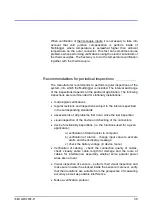
When  verification  of  thermocouple  inputs  it  is  necessary  to  take  into 
account  that  cold  junction  compensation  is  perform  inside  of 
Multilogger,  where  temperature  is  somewhat  higher  than  ambient 
temperature  on  the  outer  connector.  This  fact  can  sometimes  cause 
problems when performing verifications using the electric simulators of 
the thermocouples. The best way is to do the temperature verification 
together with the thermocouple.  


Recommendations for periodical inspections 

___________


The manufacturer recommends to  perform regular  inspections of the 
system, into which the Multilogger is included. The interval and range 
of the inspections depends on the particular application. The following 
inspections are recommended for stationary installations: 
 

  metrological verifications 

  regular revisions and inspections subject to the intervals specified 

in the corresponding standards 

  assessments of all problems that occur since the last inspection 

  visual inspection of the device and checking of the connectors 

  device functionality inspections (i.e. the functions used for a given 

application): 

a)  verification of data transfer to computer 

b)  verification  of  alarms  -  change  input  value  to  activate 

alarm and check display message 

c)  check the battery voltage (in device menu) 

  Verification  of  cabling  -  check  the  connection  quality  of  cables, 

check  visually  entire  cable  length  for  damage  and  the  route  of 
cables  for  interference,  especially  whether  some  parallel  power 
wires are not near.  

  Visual  inspection  of  sensors  -  perform  their  visual  inspection  and 

make sure no water has leaked inside the sensors; moreover, verify 
that their locations are suitable from the perspective of measuring 
accuracy as well as possible interference. 

  Make a verification protocol. 


Summary of Contents for M1200E

Page 1: ...www cometsystem com Instruction manual M1200E Multilogger ...

Page 2: ...nges in this manual without explicit agreement of company COMET System s r o All rights reserved COMET System s r o makes constant development and improvement of their products Manufacturer reserves the right to make technical changes to the device without previous notice Misprints reserved ...

Page 3: ... Main menu 20 CONNECTING WITH THE COMPUTER 24 SOFTWARE COMET VISION 25 DEVICE SETUP USING SOFTWARE 27 Device configuration basics 27 Device configuration items 27 APPLICATIONS NOTES 34 OPERATION AND MAINTENANCE RECOMMENDATIONS 38 TECHNICAL PARAMETERS 41 Power supply 41 USB communication interface 43 Measuring data memory and real time clock 43 Electromagnetic compatibility 44 Operation and storage...

Page 4: ...d quantities is 16 Finding and storing minimal and maximal values for each measured quantity since their last manual reset Acquiring autonomous time record of measured values independent of the mains supply Recorded values can be stored as separate samples in the recording time or as average minimal maximal values during the logging interval Recording may be continuous or only during an alarm opti...

Page 5: ...IE MLG M1200E 01 5 Multilogger drawing ...

Page 6: ...th proper standards Pay attention the source has undamaged cables or cover The device and power supply must not be used in a humid and hazardous environment such as bathrooms at locations exposed to direct sunlight and to other heat sources thus preventing damages and deformation of the cover Do not use the instrument without its covers Do not remove the covers from the device Do not use the instr...

Page 7: ...cted probes and your requirements If you are not going to use the device soon turn it off For more information see Chapter DEVICE SETUP USING SOFTWARE Measurements remove the Multilogger from the transportation case connect probes and external power adapter if needed and turn the device on Some device settings can be changed from its keyboard When measurement ends move the device to your computer ...

Page 8: ...ultilogger push the switch button on the device The display lights and the instrument starts working For more information see Chapter POWER SUPPLY OF MULTILOGGER Install the COMET Vision software to your computer it is available at www cometsystem com If you purchased a license for the extended SW register it Connect Multilogger with your PC for more information see Chapter CONNECTING WITH THE COM...

Page 9: ...ions and not allowed manipulations Working position of the device Multilogger placed on a horizontal nonflammable surface Multilogger fixed on the wall from nonflammable materials or in a low current switchboard using the holder the working position is with input connectors upwards Device dimensions ...

Page 10: ...10 IE MLG M1200E 01 The way of mounting the holder to Multilogger and mounting holes dimensions MLP001 MLP002 ...

Page 11: ...ctors motors frequency converters and other sources of strong interference In cable routing follow rules of standards for installation of low current distribution EN 50174 2 especially it is necessary to pay attention to avoid electromagnetic interference intrusion to the leads transmitters transducers and sensors Do not locate cabling near sources of interference Do not use leads in parallel with...

Page 12: ...12 IE MLG M1200E 01 Do not interconnect the inputs with other measuring systems Do not use common leads for several inputs ...

Page 13: ...ure stabilized Marking of subminiature thermocouple connectors and wires manufactured by OMEGA in accordance with US standard Thermocouple type Connector color wire color wire color K NiCr Ni Yellow Yellow Red J Fe Co Black White Red S Pt10 Rh Pt Green Black Red B Pt30 Rh Pt White Black Red T Cu CuNi Blue Blue Red N NiCrSi NiSiMg Orange Orange Red Two voltage ranges are available on each universal...

Page 14: ...urce is present ATTENTION never connect voltage greater than 5 5 V to the external power supply input it could damage the device Batteries _______________________________________ The Multilogger is equipped with alkaline batteries ATTENTION if you insert the NiMH charging batteries to the Multilogger change the battery model to NiMH in the device configuration Never charge batteries that are not r...

Page 15: ...n the Multilogger until you see NiMH charger on the device display The charging process is started c During fast charging Multilogger does not work in the normal operating mode does not take measurements and does not communicate with the PC d Once the charging process is completed the Multilogger displays the Batteries charged message and you can turn it off e The charging can be proceed within a ...

Page 16: ... have to make this change in the device configuration also Note The Multilogger can operate with removed batteries powered externally This is not a standard use of the device but it is possible In this case the full battery is displayed Interruption of power supply causes loss of time setting ...

Page 17: ...ortant information even under low light and from a greater distance green LED no active alarms everything is OK orange LED one alarm is active red LED several alarms are active or a system alarm device malfunction The green LED everything is OK can be deactivated in device configuration to save energy The indication LEDs can be enabled permanently or can be set to a blinking mode in battery mode t...

Page 18: ...red quantities can be optionally displayed in three different font sizes according to user needs When the smallest font size is selected up to 6 quantities can be displayed together When the largest font size is selected the maximum number of the quantities that can be displayed together is 2 The maximum range of numerical values on the display is 7 characters including the decimal point and sign ...

Page 19: ...mately one half of the battery capacity remaining battery is discharged it needs to be replaced alkaline batteries or recharged NiMH accumulators battery charging in progress the data memory limit exceeded low voltage of the real time clock circuit detected the time could be incorrect alarm at least on one channel the particular channel is marked with a bell by the given value system alarm alarm s...

Page 20: ... on the display a The dash next to the item description means that this item is not enabled for evaluation in the device configuration b The tick next to the item description means that this item is enabled in the device configuration and that it is OK c The exclamation mark next to the item description means that this item is enabled in the device configuration however it is not associated to the...

Page 21: ...re version 2 Viewing settings _______________________________ Allows to view the following settings record settings recording interval cyclic record record on alarm record of the average and min max values per logging interval general settings LCD backlight intensity battery type menu language date and time in the device alarm limits limit values hysteresis and delay for each existing channel and ...

Page 22: ...attery type menu language alarm limits limit values and alarms directions can be set for each existing channel and alarm You can switch from one channel to another using the arrow keys alarm indication enable or disable of alarm signalization optical audio Alarm out signal Setup of MUTE function temporary deactivation of audio and or Alarm out signalization memory occupation limit and signalizatio...

Page 23: ...y remain active until they are deactivated by the user They thus warn us that something was happening during the monitored period i e that the alarm limits were exceeded This function can be protected using PIN2 7 Device information _____________________________ The 32 character user description of the Multilogger device model and its serial number are displayed here The next screen displays a sum...

Page 24: ...to the computer through the USB communication interface This is way of the fast connection for short distances up to 5 m communication speed of 460 800 Bd Connect the device to the computer using the supplied cable launch the SW and add Multilogger to the list of your Comet devices ...

Page 25: ...s launched etc and will also give you access to advance functions for example charts statistical overview of the recorded data custom display export to the database etc Adding the Multilogger to the list of Comet devices _______ The device can be added by clicking on the add device button you can find it under the Welcome menu which is displayed upon the first launch of the program or also under t...

Page 26: ...___ The main menu of the program is on the right side with items Home Devices Files and Online Displays These components control appearing bookmarks Each item has its bookmarks one of them named Home is similar for all items The other options are specific for each item ...

Page 27: ...H THE COMPUTER If the Multilogger is correctly connected the Device Home panel displays its current status Click on the Configuration button The device configuration is loaded and you can view or edit it When you make a configuration change of any items the SW goes to the editing mode and limits the device access for other users now Upon a long user inactivity period the editing configuration mode...

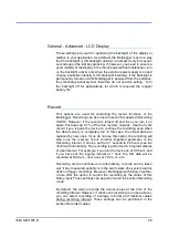
Page 28: ... date and time the recorded data in the Multilogger will have to be deleted General Advanced Energy _______________________ The Multilogger running in the standard mode will measure all inputs once per second The advantage is a fast response of the device the disadvantage is its higher current consumption if the device is powered from batteries only If you operate the Multilogger from batteries fo...

Page 29: ...he free memory capacity Use the Cyclic record if you require the device to continue the recording even when the data memory is completely full In this case the oldest data are replaced by new ones If you do not use this option the recording will stop once the memory is full Another important parameter is the Recording interval It can be set from 1 second to 24 hours see the Technical Information T...

Page 30: ...ption For a state without an alarm can be selected green LED indication When the device is powered from batteries you can select more energy economical mode under which the LED diodes only shortly blink in the case of an alarm In addition the alarm can be signaled acoustically with characteristic sound that is repeated at regular interval Service personnel can easily confirm the audio signal and t...

Page 31: ...from the keyboard or from the software COMET Vision To protect access to these functions you can use the PIN2 code which the operation personnel must enter This function deactivates enabled alarm signalizations until a new alarm occurs The deactivation can be permanent until a new alarm occurs or temporary if the alarms remain active even after selected time out the signalization is restored Alarm...

Page 32: ...quantities that you will measure on every one inputs their recording and alarm states You can see a simple list of all inputs and measured quantities on the screen First of all specify the probe or signal types connected to each input Settings button Here you also choose the measured quantities that you will acquire from this input You can also decide not to use a specific input in this case click...

Page 33: ...ine the state of the input Next you need to specify the alarm delay for the duration of which is used for eliminating short term exceeding of the limit value Hysteresis has a similar function Alarm hysteresis it is used to prevent alarm oscillation when the measured value fluctuates nearby the alarm limit We recommend not to set it at zero We have hereby completed the setup for alarm occurrence No...

Page 34: ...witch off the optical alarm signalization using the LED diodes or if necessary allow only the orange and red LED diodes working in a flashing mode while the Multilogger is powered from batteries If you are not going to use the audio alarm signalization turn it off Empty batteries can be easily recharged once the measurement is completed using the fast charge option Recommended settings for the sta...

Page 35: ... for a long time battery powered application ______________________________________ In this application the Multilogger is powered only from batteries and a fast response to changing measured quantities is not required however it is required that the device runs from the batteries as long as possible Recorded data are downloaded after measurement We recommend to use the Multilogger with NiMH accum...

Page 36: ...hnology that the Multilogger monitors A system alarm can be reported to a different person than alarms from the measured quantities Backup and restore of device configuration ____________ If you have set the whole system and you need to back up its setting with the possibility to upload it to the same or even different Multilogger download recorded data from device The saved file contains complete...

Page 37: ...e to make sure that neither the measuring ends nor conductors are connected to any conductive parts that may cause unwanted couplings This may in exceptional cases even cause damage the device If the Multilogger reports an error state you can find more information in Appendix 1 Selected error messages Another group of problems are random spikes of the measured values Most commonly they are caused ...

Page 38: ...functionality of which is depended on external power supply source Locations of temperature sensors place them to locations with sufficient air flow and where most critical point is supposed in accordance with application requirements The sensor has to be sufficiently inserted into the measured area or sufficiently connected to it in some other way thus preventing the measured values to be influen...

Page 39: ...ical verifications regular revisions and inspections subject to the intervals specified in the corresponding standards assessments of all problems that occur since the last inspection visual inspection of the device and checking of the connectors device functionality inspections i e the functions used for a given application a verification of data transfer to computer b verification of alarms chan...

Page 40: ...r Its contact is given in the warranty certificate supplied with the Multilogger ATTENTION damage due unauthorized manipulation will cause the warranty to expire Placing out of operation after the end of the device life ____ Disconnect the power remove batteries and return data logger to the supplier or specialized company as electric waste ...

Page 41: ...ilogger for NiMH accumulators Operating time of fully charged NiMH batteries 1 month in the standard measuring mode approximately 6 month in the power saving mode ________________________________________________________________________________________________ Applies to Multilogger with fully charged batteries of the recommended type when the display backlight LED indication and audio signalizatio...

Page 42: ...______________________________________________________ The Multilogger does not allow increase the supply current of the PC USB interface Therefore the fast battery charging does not have to work correctly from USB Battery charger __________________________________ Slow charging mode current approximately 10 mA Fast charging mode current approximately 350 mA _______________________________________...

Page 43: ...default 10 s in the energy saving mode Recording interval 1 s 2 s 5 s 10 s 15 s 30 s 1 min 2 min 5 min 10 min 15 min 30 min 1 hour 2 hours 3 hours 4 hours 6 hours 12 hours 24 hours Memory capacity Up to 1 000 000 values for non cyclic record Up to 600 000 values for cyclic record Duration of data downloading 5 minutes for a 100 data memory occupation using the USB interface Real time clock stabili...

Page 44: ... 4 2 class A 4 8 kV EN 61000 4 3 class A 3V m EN 61000 4 4 class A 0 5 1 kV EN 61000 4 5 class A external power supply only EN 61000 4 6 class A 3 V Operation and storage conditions Operation temperature 10 to 60 C Operation humidity 5 to 85 RH without condensation Operation environment chemically non aggressive Storage temperature 30 to 80 C Storage humidity 5 to 90 RH ...

Page 45: ... between the input connectors The inputs are not galvanically isolated from each other nor from other signals connected to the device In order to secure correct measurements you need to prevent undesirable coupling Furthermore the Multilogger has to be placed in its working position and temperature stabilized Required measured quantities can be selected for each input using the COMET Vision softwa...

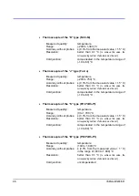
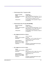
Page 46: ... corresponding number of decimals must be set Cold junction compensated in the temperature range of 10 to 60 C Thermocouple of the S type Pt10 Rh Pt Measured quantity temperature Range 0 to 1 700 C Accuracy without probes 0 3 from the measured value 1 5 C Resolution better than 0 1 C to achieve this value the corresponding number of decimals must be set Cold junction compensated in the temperature...

Page 47: ...imals must be set Cold junction compensated in the temperature range of 10 to 60 C DC voltage from 60 mV to 140 mV Range 60 to 140 mV Accuracy without probes 100 uV Resolution better than 1 uV to achieve this value the corresponding number of decimals must be set Input impedance approximately 107 Ω Minimum input voltage 0 2 V Maximum input voltage 3 V Connector miniature uncompensated thermocouple...

Page 48: ...on error The probe is probably damaged Try another probe Error 7 Pt1000 M probe communication error Check the connected probe it is probably not connected or it is not Pt1000 M line probe Error 8 Cold junction temperature measurement error The Multilogger is outside of the range of operational temperatures or the device is damaged Error 9 The value is out of the measuring range for example tempera...

Page 49: ...irable coupling among the inputs incorrect connection damaged cables damaged device Check the input connections and the connected cables Error 50 Error 53 Error 56 Device configuration error damaged configuration Download the configuration to the SW check of the settings of individual items and save them back to the Multilogger Error 51 The probe of the Digi M line contains invalid calibration con...

Page 50: ...50 IE MLG M1200E 01 Appendix 2 Input circuits ...

Reviews: