ComAp InteliVision 8 Manual Download Page 86

InteliVision 8

86

Default firmware location is the same as for firmware saving.

c:\Documents and Settings\All Users\Dokuments\ComAp PC Suite\Tools\IVProg

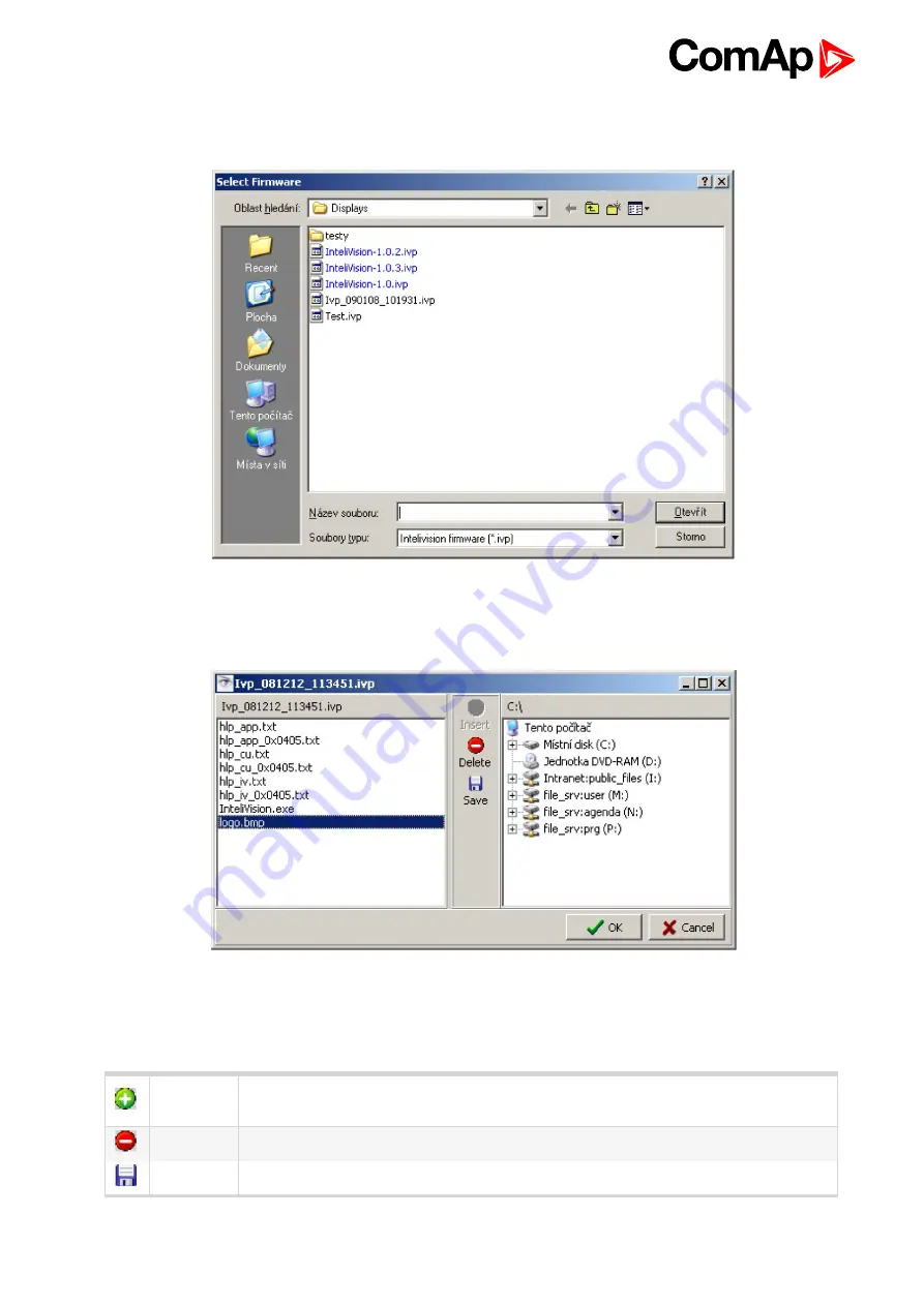
Image 10.14 Selection of firmware

When firmware is chosen a new window for firmware modification appears.

Image 10.15 Window for firmware modification

You can see the content of the firmware which is being modified on the left side and content of your computer on

the right side. You can do following changes with selected firmware.

Insert

File from your computer to the firmware (inserted files will be added to selected

firmware)

Delete

Selected file from the firmware

Save

(Extract) selected firmware file from firmware to your computer

Summary of Contents for InteliVision 8

Page 1: ...comap control com Global Guide InteliVision 8 Controller Display Unit for ComAp Controllers SW version 2 6 0 1 Document information 5 2 Applications overview 6 3 Fast navigation 8 4 Operator interface 21 5 Initial Screen 54 6 Features based on USB 56 7 Support of user s pictures 63 8 Screen modification 66 9 Installation 71 10 InteliVision 8 programming 78 11 Technical data 92 ...

Page 2: ...controller status 13 3 6 How to view a breaker status 13 3 7 How to change a Gen set mode 14 3 8 How to change setpoints 15 3 9 How to find alarms 15 3 10 Communication error 16 3 11 How to change a password to save a password to logout 16 3 12 How to change display brightness 17 3 13 Main icons description 19 4 Operator interface 21 4 1 Measurement screens 25 4 1 1 IGS NT standard measurement scr...

Page 3: ...es 52 5 Initial Screen 54 5 1 Additional information on initial screen 54 5 2 Support of customized logo 55 6 Features based on USB 56 6 1 Directory structure and names of files 56 6 2 Export of history 57 6 3 Export import of trends 58 6 3 1 Continuously saving of trends 58 6 3 2 Single export of trends 59 6 3 3 Import of TRD file 60 6 4 Export of archive and InteliVision 8 firmware 60 6 5 USB as...

Page 4: ... 76 10 InteliVision 8 programming 78 10 1 ActiveSync 78 10 2 Windows Mobile Device Center WMDC 80 10 3 IVProg running 80 10 3 1 IVProg from Genconfig 81 10 3 2 IVProg and file association 90 10 3 3 IVProg and command line 91 11 Technical data 92 11 1 Power supply 92 11 2 Operating conditions 92 11 3 Climatic mechanical and EMC standards 92 11 4 Dimensions and weight 94 11 5 Communication interface...

Page 5: ...our TFT display which helps visibility and definition for on screen information The control interface has also been updated with user friendly intuitive active buttons giving users access to more information in less time InteliVision 8 also includes features based on the USB memory stick possibility to use own pictures on the Measurement screens TRENDS monitoring helping the end user to evaluate t...

Page 6: ...eliVision 8 is supported from following versions mhx file ivp file IS NT 2 6 InteliVision 8 IG NT 2 6 IM NT 2 9 ID DCU Industrial 2 9 ID Mobile Logger 1 8 ID Mobile 1 6 PC Software InteliVision 8 is supported from the following versions PC Software GenConfig 2 6 DriveConfig 3 1 Installation Packages InteliVision 8 is supported from the following versions Installation Packages IGS NT Install Suite ...

Page 7: ... 0 New Features pdf New Features List of IG IS NT version 3 7 0 https www comap cz products detail inteligen nt basebox downloads tabshttps www comap control com products controllers gen set paralleling controllers IS2GAS 1 2 0 New Features pdf New Features List of IS2GAS version 1 2 0 https www comap cz products detail inteligen nt basebox downloads tabshttps www comap control com products contro...

Page 8: ...assword 12 3 4 How to view important values 13 3 5 How to view a controller status 13 3 6 How to view a breaker status 13 3 7 How to change a Gen set mode 14 3 8 How to change setpoints 15 3 9 How to find alarms 15 3 10 Communication error 16 3 11 How to change a password to save a password to logout 16 3 12 How to change display brightness 17 3 13 Main icons description 19 6 back to Table of cont...

Page 9: ...cts a submenu sub options Hot keys Selects main menu options Navigation buttons Arrows and buttons for movement ESC and Enter button Stop Stops the gen set Start Starts the gen set Horn reset Deactivates the horn audible alarm Power Power LED indication green power is on Controller mode Calls controller mode menu the mode can be changed then by appropriate context button Fault reset Acknowledges f...

Page 10: ...cation by pressing the context button on the right 3 Use to choose ID or IGS NT Controller see How to connect IV8 display to IGS NT or ID controller on page 10 4 Use and Enter buttons to choose Connection Type 5 Use and Enter buttons to choose Controller address address can be automatically detected 6 Use and Enter buttons to choose Terminal address address can be automatically detected 7 Use and ...

Page 11: ...ion screen and communication with the actual controller is lost It is possible to detect Controller address and terminal address on CAN Terminal address on display terminal or RS485 After detection phase the first available active address of the controller is set If you go to the list of addresses press Enter on item Controller Adr you will see green and grey numbers Green colour means that detect...

Page 12: ...ord There are two ways how to enter a password Use USB stick as a login key see USB as login key on page 61 Insert a password manually To enter a password manually 1 Press Help Others button 2 Press Users Password button 3 Use to go to Users field and press Enter 4 Use to choose a user and press Enter 5 Use to go to EnterPassword field and press Enter 6 Enter password and press Enter 7 Use and con...

Page 13: ...r Mains Gen Synchro using context buttons 3 To go up down through Measurement screens use buttons even when context menu is active Note You can use PgDn or PgUp buttons to display quickly context buttons from following page when ythez are available context menu has to be active 3 5 How to view a controller status No matter where you are in the menu you can see the status of the controller at the b...

Page 14: ...button you can find it on the right see Measurement screens on page 25 The scheme with breaker s status appears Note The Power button is available only for connection with IGS NT controller 3 7 How to change a Gen set mode To change a gen set mode 1 Press ControllerMode button at the bottom of IV8 display Available gen set modes appear e g TEST AUT MAN OFF Note Available gen set modes depend on th...

Page 15: ...se buttons to go to the character position 6 To change a value of the setpoint use buttons and press Enter Note If you insert a wrong value which is e g out of range the field colours in red You can find more information about setpoints in Setpoints screens page 40 3 9 How to find alarms To find alarms 1 If they do not appear automatically press AlarmList button 2 To go through alarms press or but...

Page 16: ...mage 3 9 Communication error When you correct the communication error the red stripe disappears but the grey inactive icon of lost communication stays visible After you press IV info button on Help Others screen the inactive icon disappears 3 11 How to change a password to save a password to logout To change a controller password 1 Log in see How to enter a password on page 12 2 Press Help Others ...

Page 17: ...s not to change passwords And every user is able to change its own password Note For ID Only the user with the third access level is able to change passwords of other users And every user is able to change its own password 3 12 How to change display brightness There are two brightness settings available Day mode Night mode especially for Marine application Quick alternation between modes can be do...

Page 18: ...or ESC PgDn buttons switches between modes which shall be adjusted when dialog for changing of intensity brightness is active How to change display brightness page 17 How to change display brightness page 17 Image 3 11 Day mode brightness setting ...

Page 19: ...omAp User User name Open green lock and display is NOT locked user is logged in 7 a user has assigned access level 7 Display or setpoint is locked user is NOT logged in with sufficient password level PageMode is On in History or Trend screen Zoom 10x Blue icon USB stick plugged on Bed icon data is written to USB stick Green icon data is read from USB stick ...

Page 20: ...isplay Icon is shown trends are running Icon is NOT shown trends are NOT running Access lock is active display is locked for security reasons Remote communication appears when any remote connection to controller is active Blinking exclamation mark a new alarm occurred After enter of AlarmList the exclamation stops blinking Blue ringlet opened Green circle closed Red circle MCB GCB fail ...

Page 21: ... IGS NT controllers 43 4 4 2 AlarmList for ID controller 46 4 5 History screen 47 4 5 1 History context buttons 47 4 5 2 Change of an order of columns 48 4 5 3 Help Others screen 48 4 5 4 Help context buttons 50 4 6 Rules for help customization 50 4 6 1 How it works 50 4 6 2 Text formatting rules 51 4 6 3 Other important rules 52 6 back to Table of contents This chapter provides information on how...

Page 22: ...he horn audible alarm Power Power LED indication green power is on Controller mode Calls controller mode menu the mode can be changed then by appropriate context button Fault reset Acknowledges faults and alarms active only in Alarm screen Alarm Alarm LED indication yellow alarm of the first level e g warning red alarm of the second level e g shutdown Engine Engine LED indication green the engine ...

Page 23: ...linders engines etc Trends Display of chosen values in graphs real time trends Setpoints Setpoints setting AlarmList List of actuve and or unacknownledged alarms History Display of history records Help Others Settings info users passwords communication languages IV and controller info IV settings Image 4 3 Navigation buttons ...

Page 24: ...s when menu is not active Quickly goes down among context menu items or records similarly as PgUp Escape from any dialog window or menu cancels an action Jump to Main Measurement screen Confirms a value or opens a value adjustment within setting dialogs Movement left Movement right Movement down Movement up Note To leave the menu use Esc Enter or buttons ...

Page 25: ...ed context menu Note The icon in the bottom right hand corner see Measurement screens on page 25 indicates possibility to use button to see buttons of the next page context menu To go directly to a concrete Measurement screen choose the appropriate context button Measurement screens page 25 or use buttons to go through measurement screens Passage through screens is cyclic it means the passage from...

Page 26: ... Mains Gen Synchroscope Statistics Analog Inputs Binary 1 0 Other screens can follow depends on controller configuration ECU extension modules etc Image 4 6 Main screen Note What do numbers in the bracket 1 4 in the top of screen mean The first number is the number of a screen sequence The second number is total number of screens in Measurement block ...

Page 27: ...InteliVision 8 27 Image 4 7 Power screen Image 4 8 Main screen ...

Page 28: ...InteliVision 8 28 Image 4 9 Gen screen Image 4 10 Synchroscope screen ...

Page 29: ...InteliVision 8 29 Image 4 11 Statistics screen Image 4 12 Analog Inputs screen ...

Page 30: ...ing order Main Analog inputs Binary 1 0 Statistics Other screens can follow depends on controller configuration ECU extension modules etc Note What do numbers in the bracket 1 4 in the top of screen mean The first number is the number of a screen sequence The second number is total number of screens in Measurement block Image 4 14 Main screen ...

Page 31: ...InteliVision 8 31 Image 4 15 Analog inputs screen Image 4 16 Binary 1 0 screen ...

Page 32: ...InteliVision 8 32 Image 4 17 Statistics screen ...

Page 33: ...ends screen appears curves are just and example Image 4 18 Trend context menu Note Buttons Channels Settings Zoom 10x 1x Markers On Off are available only when trends are NOT running 4 2 1 Trends context buttons Trend Context buttons Start Starts trends logging Channels Selects displayed values and sets their parameters Settings Sets trends properties Zoom 10x Switches zoom of curves 1x 10x Marker...

Page 34: ...ues press Channels button The following screen appears Image 4 19 Channel set menu To change a value or to choose a new one in unallocated channel use buttons to move up and down in the column Value and press Enter Image 4 20 Channel trends settings Use buttons in the left column to select a group of values Use buttons to go to the right column use buttons to select a certain value and press Enter...

Page 35: ...e color of the trend curve and press Enter Image 4 21 Choosing of a trend line color Use button to go to button and confirm the action by pressing Enter Binary value selection When binary value is selected in Trend channel dialog there is displayed binary information indicating visibility of particular bits of binary signal in Trend screen see Trends channels on page 34 In default all bits are sel...

Page 36: ...rt run modes of trends and type of storage Press Settings button The following screen appears Image 4 23 General settings of trends Use buttons to choose Grid density Similarly choose Sample period of trends in seconds 1 second is a minimum 7200 second i e 2h is maximum Choose button to start trends using the Start button from Trends Context menu or ...

Page 37: ...ne Press button to confirm or button to cancel the setting adjustement Note When the trends are in the cyclical mode and the memory is full the oldest data are overwritten e g when the sampling period is 1 minute and 8 channels are configured the memory is full approximately in a month 4 2 4 Export import of trends The function is described in subchapter Export import of trends page 58 4 2 5 Verti...

Page 38: ...irst one is allowed by pressing button if you are using for going though trends these buttons combination if you use arrows for going through trends Note More than one screen of trend should be displayed on screen to be cyclic scrolling active 4 2 7 Availability of disk space Availability of disk space reserved for trends is now displayed in time format Displayed time information is placed in the ...

Page 39: ... continuous logging of trend is selected the time information is relating to free space of connected USB storage The maximal displayed time is 99 years When value of available space is bigger information 99 years is displayed Time format of available space dd hh mm yy dd hh 99 years ...

Page 40: ...Reference Guide of the specific application e g IGS NT SPTM 2 6 Reference Guide pdf or IGS NT MINT 2 6 Reference Guide pdf or other There is also allowed the cyclic movement among Setpoints Screens and also among items in particular Setpoints groups Scroll bar in the right side of the Setpoints Group determines position in setpoint list The value of Setpoint can be Strictly numerical value Text li...

Page 41: ...th a numerical value 3 Use buttons to go to a certain position of the field and use buttons to change the value Then press Enter For quicker movement among value positions it is possible to move cyclic through value with using buttons It means from the highest digit place to the lowest digit place and vice versa Note If you set the value out of limit the field will color red and you will not be ab...

Page 42: ...e button from the context menu on the right e g Basic settings 2 Use to go to a certain setpoint e g Governor mode and press Enter see Text string selection on page 42 Image 4 28 String value selection 3 Use to select the string from the list and press Enter ...

Page 43: ...one for IGS NT controllers and the second for ID controllers First see the description of the AlarmList for IGS NT controllers 4 4 1 AlarmList for IGS NT controllers When an error occurs a new alarm appears in the AlarmList screen and exclamation mark appears on the front panel of IV8 display and together with Alarm LED start blinking see AlarmList for IGS NT controllers on page 43 When AlarmList ...

Page 44: ... screen Note For ID Fault Reset button is active only in AlarmList screen A error must be confirmed with Fault Reset button If you resolve the error before pressing Fault Reset button the alarm still remains in the AlarmList it will turn black till you press Fault Reset button When the number of alarms is up to 4 the alarms are displayed in bigger font to be better visible from longer distance fro...

Page 45: ...alarms in AlarmList Alarm summary taken from the left AlarmList for IGS NT controllers page 43 White number Number of active alarms Halved asterisk Sum of unacknowledged active and inactive alarms Sum Total sum of alarms Image 4 32 Alarm summary ...

Page 46: ...ers see the description above however there are some differences There are two separate columns of alarms AlarmList for ID controller page 46 The left column for ID controller The right column for ECU To move between ID and ECU alarms in AlarmList use buttons Fault Reset button confirms either ID or ECU alarms Image 4 33 ID controller alarm list ...

Page 47: ...he first column is RPM by default it is not possible to move columns Reason Date and Time First Row Jump to the first row First Col Jump to the first column Last Col Jump to the last column PageMode On When the PageMode is ON you can use buttons to jump by page right or left quicker movement through columns Icon at the top of the screen indicates that PageMode is On History USB Automatic export hi...

Page 48: ...esired position Press Enter to confirm the new position of the column or press ESC to cancel the action 4 5 3 Help Others screen In Help Others submenu you can see context menuHelp Others screen page 48 Help Others screen page 48 with other settings passwords setting communication setting language selection IV8 setting Export to USB and information various helps IV8 and controller info and etc As ...

Page 49: ...InteliVision 8 49 Image 4 36 Help Others screen part 1 Image 4 37 Help Others screen part 2 ...

Page 50: ...81 hlp_xxx can have following structure hlp_nt txt Using this file you will replace CU Alarm Help for IGS NT controllers hlp_id txt Using this file you will replace CU Alarm Help for ID controllers hlp_app txt Using this file you will create Application Help for all controller types hlp_iv txt Using this file you will replace InteliVision help These 4 help types above are independent on language s...

Page 51: ...ertain language is chosen in controller it looks for help in such a language In case it is not present it looks for help which is independent on language selection When these are not present then default helps which are included in InteliVision8 exe file are used The default helps are not customizable 4 6 2 Text formatting rules There are several tags which you can use for text formatting Header h...

Page 52: ...ere is a special tag for creating new line In case you use Enter in text file what appears in text editor as 3 new lines there won t be new line on InteliVision 8 screen visible there will be just a rectangle sign For more details see Other important rules on page 52 There is no tool for automatic page splitting It is up to customer to decide where to put beginning of new page In case that there i...

Page 53: ...ag lt br gt new line with normal high is generated br h font color 5 New paragraph font h Do not use paired tag lt gt lt gt in case you want to have an end of paragraph p After this tag lt p gt new line with 1 5 row height will be generated p h font color 9 Bold text font h Enclose text between opening tag lt b gt and closing tag lt b gt to get text in b BOLD b h font color 10 Italic text font h E...

Page 54: ...mation is visible on init screen before the connection between display and controller unit is established It means you don t need to connect to any controller to find out following information SW Version SW Version of the running software HW Version HW Version of InteliVision unit Release Date Running software Release Date Serial Number Serial Number of InteliVision unit Core Version Core Version ...

Page 55: ...rmware upgrade using IVprog from version 1 1 Logo requirement Name of the file has to be logo bmp It has to be in bmp format Resolution 800x510 pixels Colour depth up to 24 bits Note Another name than logo bmp is not supported Note Background with logo bmp picture has been removed from IV info and ControllerInfo screens due to risk that important information wouldn t be visible in combination with...

Page 56: ... opposite case the icon is missing During of USB storage operation the blue color of USB icon changes color according to type of operation When data is exported from InteliVision 8 the icon is red when data is imported the icon is green Image 6 1 USB stick connected icon 6 1 Directory structure and names of files All files exported from IV8 are stored in specified location Directory structure on U...

Page 57: ...ll not be saved 6 2 Export of history User can very easily download and save History from InteliVision 8 to USB storage For this purpose the new item Export USB was introduced in History context menu This item is available when the USB storage is plugged in The history file is exported to the History folder in dedicated folder structure created automatically after plug in USB storage The history f...

Page 58: ... to be set up in Trends context menu Settings Storagesee Continuously saving of trends on page 58 There are three possibilities i e Memory only USB Mode 1 USB Mode 2 Image 6 4 Settings dialog Data is saved in file with extension TRD Data is saved with respect to Channel setting If a user changes Channel setting it will be created another new file where data will be saved Similarly in case when int...

Page 59: ...cel Single export of trends page 59 Selection of file format can be done in Select exported data format pop up window which appeared when user press Export USB item in Trends context menu Image 6 5 Select exported file format pop up window File format definition trends genset name date time STD trends genset name date time CSV Difference between winscope and csv format STD CSV Channel definition Y...

Page 60: ...ion 8 firmware The possibility to save archive to USB storage is given by new item in Help Others context menu The item is called Export USB and it is available if the USB storage is plugged in When a user enters this item the pop up window Select exported data gives you two choicesExport of archive and InteliVision 8 firmware page 60 Export Controller ANT archive Export InteliVision IVP firmware ...

Page 61: ...e time IVP Example backup 2 0 07 11 11 13 58 16 IVP 6 5 USB as login key This feature allows that a user can log in very quickly to the InteliVision 8 with proper security level without typing of password manually The login information is automatically loading from USB stick The login information is saved in PASSWORD folder in file with dedicated file definition password genset name txt Example pa...

Page 62: ...he Login window automatically appears and after confirmation by Enter button user is logged in InteliVision 8 with proper security level This status in indicated by green icon in upper right corner of screensee USB as login key on page 61 Image 6 8 Icon of login key usage In case that user unplugs USB after USB login the user will be automatically logout Image 6 9 Save password button in logout di...

Page 63: ...ge with IVI extension A picture package is possible to create in Picture Manager which can be launched also from Genconfig or IVProg Picture Manager allow manage more picture packages including uploading package to InteliVision 8 IMPORTANT Picture package added in IVProg to I should MANUALY be uploaded IV8 SEPARATELY by using USB cable likewise as during Firmware update When Picture Packages is cr...

Page 64: ...InteliVision 8 64 Image 7 1 Using user s Picture for screen definition 1 Image 7 2 Using user s Picture for screen definition 2 Supported picture formats BMP JPG PNG ...

Page 65: ...ize When bigger picture is used it will be automatically crop The memory of InteliVision 8 is not unlimited Amount of pictures which user can use is depended on size of of pictures Approximately it is possible to use 5 6 pictures of maximal size for one screen IV8 has implemented watchdog for size memory When the limit is increased warning message is displayed IMPORTANT User s pictures occupy all ...

Page 66: ... the main screen of InteliVision 8 8 1 User definable SoftKeys buttons The user has possibility to assign various functions to SoftKeys buttons buttons on the bottom of Intelivision see User definable SoftKeys buttons on page 66 Different functions can be assigned to any SoftKeys button of any screen The functions can be easily defined in new graphical Screen Editor SE Pre defined functions Fast j...

Page 67: ...cond button is associated with fast link to Binary I O in Measurement and the third button is associated with RemoteSwitch 1 which is used as toggle button Labels on buttons are customizable Note The name of buttons Horn Start Stop is not possible to change Note Functions and Commands assigned to buttons in IV8 of actual archives are default Image 8 2 User buttons ...

Page 68: ...ould be chosen as text color of variables and values during screen modification or color of line objects etc Current version supports 255 new color plus color from previous IV8 version All color can be chosen from color palette implemented in Screen Editor see Support of color palette on page 68 Image 8 3 Color palette ...

Page 69: ...ncy attribute New attribute transparency was added to Measurement objects It means that each graphical object can have transparent background Transparency attribute page 69 how this parameter is possible to use Image 8 4 Transparency ...

Page 70: ...ent of the Tier 4 Final standard InteliVision 8 supports the symbols concerned to the Tier 4 Final regulation see Support of Tier 4 Final symbols on page 70 Image 8 5 Tier 4 Final symbols Illustrative Picture Note The entire list of the available Tier 4 Final icons are accessible in the Screen Editor utility in GenConfig ...

Page 71: ... wiring 72 9 3 1 ID Mobile wiring 74 9 4 Modules address combination on CAN IG IS NT ID 75 9 4 1 IGS NT controllers and 4 InteliVisions 8 on CAN2 76 9 4 2 ID DCU Marine controller and up to 8 InteliVisions 8 on CAN2 76 6 back to Table of contents 9 1 Terminals and dimensions Image 9 1 Terminal dimension ...

Page 72: ...InteliVision 8 72 9 2 Mounting system Image 9 2 Mounting system 9 3 Recommended wiring Image 9 3 IG NT wiring ...

Page 73: ...InteliVision 8 73 Image 9 4 IS NT wiring Image 9 5 InteliDrive DCU wiring ...

Page 74: ...lso to ID Mobile ID Mobil has 2 communication interfaces which can be used for communication with InteliVision 8 RS485 CAN2 Since ID Mobile has a waterproof cover it has not free accessible communication ports All ports and inputs output are merged to 2 large waterproof connectors Image 9 7 ID Mobile and connectors ...

Page 75: ...r to the corresponding chapter or reference guide for detailed description Real CAN2 Address IG MU I LB I LB modem I LB IG IB IBConfig 1 5 IG IB IBConfig 1 6 IV 8 I RD CAN 122 addr 2 addr 4 addr 4 123 addr 2 addr 2 addr 1 addr 1 addr 2 addr 2 addr 2 124 addr 1 addr 1 addr 2 addr 2 addr 1 addr 1 addr 1 125 modem addr 1 addr 3 addr 3 Image 9 9 CAN2 Address occupation Note Please note that USB port i...

Page 76: ...anAddrSwitch2 Modem address 2 default value InteliVision 8 Terminal 4 In summary a user can decide if he uses max 2 InteliVisions 8 and 2 modems on CAN2 bus or uses modem addresses for connection of 2 additional InteliVisions 8 on CAN2 totally he has 4 InteliVisions on CAN2 9 4 2 ID DCU Marine controller and up to 8 InteliVisions 8 on CAN2 4 InteliVision on CAN2 Currently the maximal number of the...

Page 77: ... to 8 InteliVisions 8 on CAN2 page 76 with using two ID DCU Marine controllers which are separated by I CR ComAp CAN repeater This feature is supported form firmware version ID DCU Marine 1 7 or newer Image 9 10 ID DCU Marine and 8 InteliVisions 8 on CAN2 The fourth InteliVision 8 terminal addr 3 has to be enabled in the same way as was described above in the chapter ID DCU Marine controller and u...

Page 78: ...matically To make IVProg running you also need to install Microsoft ActiveSync for Windows XP or Microsoft Windows Mobile Device Center WMDC for Windows Vista or WIN7 You can download these drivers from Microsoft web page https www microsoft com To install these drivers properly follow Microsoft instructions IVprog SW support 64 bit Windows Vista and Windows 7 10 1 ActiveSync When InteliVision 8 i...

Page 79: ...Vision 8 upgrade purpose and press Next Also main ActiveSync window appears Image 10 2 ActiveSync Main window If you need you can change the communication settings File Connection Settings see ActiveSync on page 78 Image 10 3 ActiveSync connection setings ...

Page 80: ... above Note If you use Windows Vista SP1 has to be installed to make the IVProg running properly WMDC behavior is analogical to ActiveSync behavior except you don t have to Set Up a Partnership Note To see what PC software versions support IV see Firmware and PC Software Supporting InteliVision 8 chapter Image 10 4 Window Mobile device center 10 3 IVProg running IVprog is tool which serves for pro...

Page 81: ...InteliVision 8 81 10 3 1 IVProg from Genconfig Image 10 5 GenConfig and InteliVision 8 SW upgrade Image 10 6 DriveConfig and InteliVision 8 SW upgrade ...

Page 82: ...owing window appears Image 10 7 IVProg main window There are several possibilities in what you can do in IVProg Read firmware page 83 Write firmware page 83 Manage firmware page 85 Read pictures page 87 Write pictures page 88 Manage pictures page 89 ...

Page 83: ...firmware is automatically created and it contains information about date and time Ivp_ YYMMDD _ HHMMSS ivp Write firmware The selected firmware is uploaded to InteliVision 8 by touch of this button Firstly window for selection of IV8 firmware appears After choosing the appropriate firmware and its confirmation a warning message if cable between PC and InteliVision is connected appears Write firmwa...

Page 84: ...p of InteVision 8 firmware The backup firmware you can find in c Documents and Settings All Users Dokuments ComAp PC Suite Tools IVProg After that window which compares files contained in an old and a new firmware appears Left side corresponds to old firmware version and right side corresponds to the new firmware version In this step files cannot be modified so if some files in new firmware are mi...

Page 85: ...hat files should be included in the firmware and which not The only obligatory file which has to be present is InteliVision exe file all the others are optional InteliVision exe Obligatory file Logo bmp Optional file hlp_iv txt Optional file hlp_app txt Optional file hlp_nt txt Optional file hlp_id txt Optional file hlp_xx_langID Optional file where xx iv app nt id langID ID of any supported langu...

Page 86: ...ication appears Image 10 15 Window for firmware modification You can see the content of the firmware which is being modified on the left side and content of your computer on the right side You can do following changes with selected firmware Insert File from your computer to the firmware inserted files will be added to selected firmware Delete Selected file from the firmware Save Extract selected f...

Page 87: ...ress OK save the modified firmware Read pictures This function allows downloading pictures which are currently present in IV8 to your PC When you click on Read Pictures button Save As window appears see the picture below and you can choose a location where you would like to save the downloaded pictures Image 10 16 Downloading of IVI package of pictures Name of the IVI package is automatically crea...

Page 88: ...ension When you click on Write Pictures button Select window appears see the picture below and you can choose a location where your IVI package is prepared Note Image Manager can be launched directly from Screen Editor or from IVProg Image 10 17 Uploading of IVI package of pictures When uploading is finished correctly following dialog appears In other case error dialog appears ...

Page 89: ...InteliVision 8 89 Manage pictures This function launches Picture package Manager see Manage pictures on page 89 where package of pictures can be modified Image 10 18 Image picture Manager and Editor ...

Page 90: ... uploaded to IV8 Picture Package Manager is possible to launch also from Screen Editor Note When package is read written to IV8 InteliVision 8 has to be connected with PC with A B USB cable 10 3 2 IVProg and file association IVP file firmware and an IVI files package of pictures are associated with IVprog application and according to their extension corresponding function is automatically started ...

Page 91: ...V8 Launching of IVProg graphical interface Detail description of commands Uploading of package of user s pictures to IV8 IVI file IVProg exe w inputPicturesFilename ivi Downloading Uploading of package of user s pictures from IV8 IVI file IVProg exe r C DirName outputPicturesFilename ivi Uploading of firmware to IV8 IVP file IVProg exe w inputFirmwareFilename ivp Downloading of firmware from IV8 I...

Page 92: ...Controller IV Display Voltage supply 8 36V DC 8 36V DC Consumption depends on supply voltage 0 4A at 8VDC 1A at 8VDC 0 15A at 24VDC 0 35A at 24VDC 0 1A at 36VDC 0 25A at 36VDC Power dissipation 9 W 11 2 Operating conditions Operating temperature 20 70 C Storage temperature 30 80 C Flash memory data retention time 10 years Protection front panel IP65 Humidity 95 without condensation IEC EN 60068 2 ...

Page 93: ... EN 60068 2 6 test Fc 5Hz 25Hz 1 6mm 25Hz 100Hz 4g Flammability EN 60695 11 5 05 High Voltage Germanische Lloyd spec VI Part 7 14 Power supply terminals against box Uef 572 V duration 1 min Insulation resistance Germanische Lloyd spec VI Part 7 13 Electrostatic discharge EN 61000 4 2 6kV contact discharge 8kV air discharge Radiated elmag field immunity EN 61000 4 3 Fast low energy transients burst...

Page 94: ...ed emissions CISPR 16 1 CISPR 16 2 Radiated emission from enclosure CISPR 16 1 CISPR 16 2 Conducted low frequency interference Germanische Lloyd spec VI Part 7 20 11 4 Dimensions and weight Dimension Front panel 289 5 x 186mm Rear cover 278 60 x 175 6x33 60mm InteliVision 8 cutout 178 x 282mm Weight 1600g ...

Page 95: ...r1 pdf USB Slave USB slave for system administration only is accessible without cover removal USB Master USB Master is determined for features based on USB See chapterFeatures based on USB page 56 11 6 Operating system Windows CE 6 0 operating system 11 7 LCD display 8 color TFT display with resolution of 800 600 pixels LCD display active area dimension 162x121 5mm Pixel size 0 2025 W x 0 2025 H m...

Page 96: ...nition of contrast ratio Contrast ratio CR Luminance measured when LCD on the Black state Luminance measured when LCD on the White state Note All input terminals LCD panel must be ground while measuring the center area of the panel The LED driving condition is IL 20mA of which each LED module is 3 LED serial ...

Reviews: