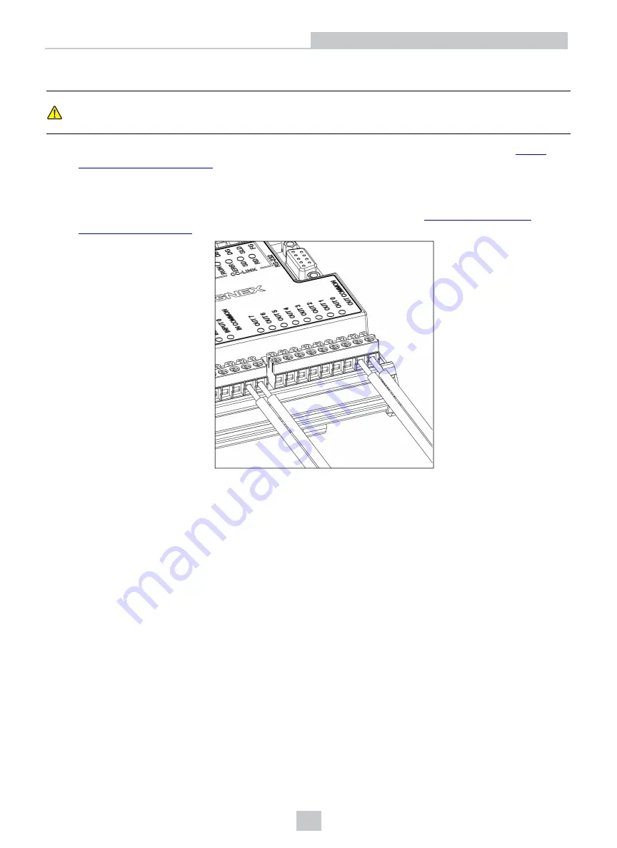
Connect the Input and Output Wires (Optional)
CAUTION
:
When connecting the In-Sight 7000 series vision system to the CIO-MICRO or CIO-MICRO-CC I/O
module, the I/O module's , TRIGGER-, HS OUT 0, HS OUT 1 and HS COMMON terminals are not
supported. Do not connect wire leads from remote devices to these terminals.
1. Determine how I/O devices will be connected to the I/O module’s input and output terminals. Refer to
for common wiring configurations.
2. Use a screwdriver to loosen the appropriate screw terminals.
3. Insert the input and output wires (16 - 22 AWG, solid or stranded wire) to the input and output terminals. Connect
the other end of the input and output wires to the applicable I/O device. Refer to
for port and terminal block pin assignments.
4. Tighten the screw terminals with the screwdriver to secure the wire leads in the terminal block; the maximum
torque is 0.1921 Nm (1.7 in-lb).
15
Installation


