6
INSTALLATION PROCEDURES –
Plumbing
CHAPTER 4
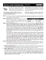
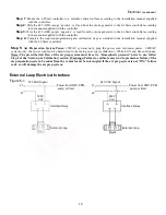
The ozone system should be plumbed using either a sidestream or full flow configuration. The
sidestream loop method takes
a portion
of the water from the main flow (see Figure 4-1) and
diverts it into a sidestream
downstream
of the filter (if so equipped). Ozone is introduced into the
sidestream water and is allowed contact time with the water before it is returned to the main flow
at a point downstream of all other equipment (heaters, solar panels, etc., if so equipped) in the
circulation system. A booster pump is usually employed to compensate for the flow restriction
caused by the sidestream loop and the injector manifold. If a halogen-type residual sanitizer is
utilized, its injection point should be as far downstream as possible from the point at which the sidestream water returns to
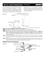
the main flow. In a full flow configuration, the same system components are usually involved and appear in the same
order with respect to the direction of flow. However,
all
the water in the main flow is allowed contact time with the ozone
(see Figure 4-2). A booster pump may be necessary to maintain proper flow requirements. If employed, the booster pump
is located
upstream
of the point at which the ozone injector manifold is installed.
NOTES:
• Adequate use of unions and isolation valves is
strongly recommended to facilitate maintenance
and repairs.
• Use Schedule 80 PVC for all plumbing connections
wherever possible. Plumbing size requirements
are dictated by the water flow characteristics of
the system.
• Make sure to use proper plumbing practices and
secure all plumbing and system equipment
according to local codes.
• Ozone is a powerful oxidizer and will degrade certain
materials. Use ozone-compatible plumbing materials
for section(s) of the system that will come in contact
with ozone dissolved in water. The following is a list of
materials that are compatible with ozone:
• PVC
• Stainless Steel (300 series)
• CPVC
• Viton
• Kynar
• EPDM
• Teflon
• Concrete
• Depending on the application, other components (psi
gauge, flow meter, etc.) may be installed to assist in
monitoring system parameters.
Step 1:
Arrange the ozone system equipment (booster pump, injector and contact vessel) according to mechanical print
or as dictated by equipment layout and serviceability considerations. Do not secure booster pump and contact
vessel to housekeeping pads at this point. Dry fit plumbing as appropriate to insure proper fit and location
before making permanent connections.
Step 2:
Install a tee or plumbing saddle into the main water line after the filter (if so equipped) and before the flow
diversion mechanism. The purpose of the mechanism is to restrict water flow so water is diverted into the
sidestream (see Figure 4-1). If such a mechanism is not present in the system (such as a heater bypass valve,
etc.), it will require installation of a valve (butterfly, gate or ball) or a flow controller.
Step 3:
Plumb a line from the tee or plumbing saddle to the booster pump. For serviceability of the equipment in the
sidestream loop, be sure to install an isolation valve between the tee or saddle and the booster pump.
Step 4:
Plumb from the booster pump to the injector manifold. Make sure to note the correct direction of flow, indicated
by a blue arrow on the inlet side of the manifold body. The check valve assembly is strapped to the manifold
using wire ties. Remove the assembly; using Teflon® tape, install it onto the top opening of the injector.
Step 5:
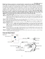
Plumb from the injector manifold to the inlet side of the contact vessel. To reduce possible backpressure to the
injector, minimize the number of elbows between the injector manifold and contact vessel. The contact vessel is
a specified size, determined by water flow requirements. ClearWater Tech contact columns and the 30, 40, 80,
and 120-gallon contact tanks have inlet
and
outlet fittings on the bottom of the vessel and are designated with
arrows showing the direction of flow
. Note: The inlet and outlet arrows on the contact tanks are under the
base of the tank.
The inlet on the 264, 463 and 850-gallon tanks is located at the top with the outlet at the
bottom.
Step 6:
Using a tee or plumbing saddle, plumb from the outlet of the contact vessel back into the main water line. For
serviceability of the equipment in the side stream loop, be sure to install an isolation valve between the outlet
fitting on the contact vessel and before returning to the main water line.
Step 7:
Secure the booster pump and contact vessel to solid mounting surfaces using appropriate hardware and
according to local codes. If installing a ClearWater Tech contact column, use a ClearWater Tech contact


