Maintenance
(continued)
17
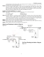
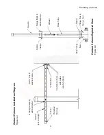
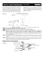
Ozone Generator Cooling Fan Assembly
Figure 8-2
System Shutdown Procedures
CAUTION:
The ozone generator operates at high voltage. Follow these steps carefully before performing any
semi-annual or annual maintenance procedures.
Step 1:
Turn off power to any peripheral system hydraulic components and air prep system.
Step 2:
Turn the Main Power switch on the ozone generator to the “OFF” position. The Ozone Generator Main Power
Light at the bottom of the ozone generator and “Ozone Output” LED(s) at the front cover should
not
be
illuminated.
Step 3:
Disconnect the power to the ozone system either at the service disconnect box (if so equipped) or main circuit
breaker.
Semi-Annual Procedures
CAUTION:
Follow system shutdown procedures (outlined above) before performing any of the following steps.
Air Preparation System
•
Air Inlet Filter: Replace the air compressor inlet filter on each air preparation system module (see Figure 6-2).
Note: Manufacturers' recommended replacement interval is 4,000 hours of operation. Operating conditions
in the equipment area will dictate the required frequency of this procedure
.
Annual Procedures
CAUTION:
Follow system shutdown procedures before performing any of the following steps.
Air Preparation System
•
Compressors: Following the procedures outlined in the compressor rebuild kit, rebuild the two compressor heads
on each air preparation system module (see Figure 6-2).
Note: Manufacturers' recommended interval is 5,000
to 12,000 hours of operation.
Compressor performance and/or operating conditions in the equipment area
will dictate the required frequency of this procedure.
Ozone Generators
•
Cooling Fan Filters: Clean or replace the cooling fan filter elements as required.
•
Inline Filter: Replace the inline particulate filter.
•
Reaction Chambers: Remove and disassemble one reaction chamber according to the steps outlined below (see
Figure 8-3). Check the chamber interior and dielectric tube for oil, dirt or moisture.
Note: CWT pressurized
reaction chambers are anodized blue.
Removal and Disassembly
Note: Disassembly and service of the reaction chamber is a technical, delicate and critical procedure. Please
consult your ClearWater Tech dealer before attempting this procedure.
Step 1:
Make sure all power to the ozone generator has been disconnected according to the “System Shutdown
Procedures” outlined above.
Step 2:
Unplug the electrical connections from the drive module.
Step 3:
Remove the 4-20mA control board with mounting bracket from the reaction chamber of the CD1500P.
Step 4:
Disconnect tubing connections from the fittings on both ends of the reaction chamber.
Step 5:
Disconnect the high voltage lead from the drive module.
Step 6:
Remove reaction chamber from ozone generator.
Step 7:
Remove retaining screws from the two end caps (4 each).
Step 8:
Using a gentle back-and-forth twisting motion, remove the non-high voltage end cap (the one
without
the white
power lead attached) from the heat sink/cathode assembly.
Note: The stainless steel clamp must not be
removed.
Step 9:
Remove the high voltage end cap and dielectric from the heat sink/cathode assembly.
Note: The stainless
steel clamp must not be removed.
Fan Filter Grill
Fan
Finger Guard
Ozone Generator Bottom Panel
Fan Filter Element

