


13
START-UP & CALIBRATION
CHAPTER 7
The previous sections of this manual have involved comparatively static procedures – making
electrical and pneumatic connections, fitting pipe, etc. This section involves the dynamic process of
starting up and balancing the components of the ozone system, including initiating water flow,
making air and water flow adjustments, etc.
Maximum performance and reliability is achieved when the prescribed air flow is maintained at the ozone generator while
the system is operating under pressure. Air from the air preparation system is flowing
through
the ozone generator under
pressure, and
from
the ozone generator under a slight vacuum (created by the ozone injector manifold). The change from
pressure to vacuum occurs after the stainless steel ozone outlet needle valve on the ozone generator.
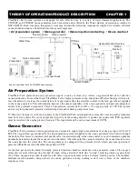
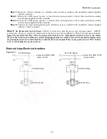
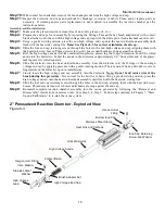
Air Preparation System, Ozone Generator & Ozone Injector
Warning:
Disconnect the External Loop dry contact from the ozone generator while performing all start-up
procedures.
Failure to do so may result in ozone escaping to atmosphere.
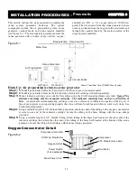
Step 1:
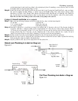
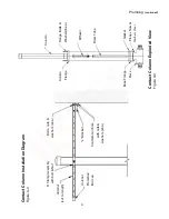
Make sure all isolation valves in the ozone water system are open (Figures 4-1 or 4-2 show recommended
isolation valve locations).
Step 2:
Start-up hydraulics. Allow the water system to reach hydraulic equilibrium (contact vessel full, off-gas vent
operating, etc.) and observe for plumbing leaks.
Note: Water flow
must
be established through the main
water pump and the ozone system booster pump (if so equipped).
Step 3:
Close the ball valve on the injector manifold about half way.
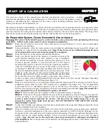
Step 4:
Using your thumb, check for the presence of vacuum (suction) at the
ozone injection manifold check valve assembly or use a ClearWater
Tech vacuum test assembly to check vacuum at the injector port. If no
suction is present, continue to close the ball valve on the injector
manifold until vacuum is detected. If using the vacuum test assembly,
check the VAC/PSI gauge for vacuum. If the needle is in the red zone
on the pressure (PSI) side of the gauge, gradually close the ball valve on
the injector manifold until the needle moves into the green zone. If the
needle is in the red zone on the vacuum (in.Hg) side of the gauge,
gradually open the ball valve on the injector manifold until the needle
moves into the green zone. While vacuum is in the green zone you must
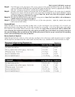
be able to achieve proper SCFH (Standard Cubic Feet per Hour) of air flow (see the “Pneumatic Operating
Parameters” chart for venturi SCFH required, Figure 7-1).
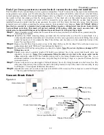
Step 5:
Make sure electrical power is on to all ozone system electrical components. The main power switch of the air
preparation system must be in the “ON” position (if so equipped) (see Figure 6-2). The air preparation
system must be set to “atmospheric pressure” prior to full start up of the system. Disconnect the oxygen
delivery line from each oxygen concentrator (if delivery has already been attached).
Note: This should have
been completed in Step 5 of “Installation Procedures - Electrical.”
Step 1:
Check to make sure the compressor of the air preparation system is operating.
Step 2:
Using the air flow gauge adjustment valve on the air preparation system (see Figure 6-2), adjust the
air flow according to the “Air prep system air flow” specifications outlined in Figure 7-1.
Note: When the
system is under normal operation, the air flow will drop from the initial setting due to the air
preparation system being under back pressure.
DO
NOT
READJUST THE AIR FLOW GAUGE
ADJUSTMENT VALVE.
Step 6:
Connect the Teflon
ozone delivery line from the vacuum break to the ozone inlet fitting located at the ozone
injection manifold check valve assembly.
Step 7:
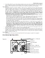
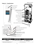
Using the stainless steel ozone outlet needle valve located at the bottom the ozone generator (see Appendix,
Section A), adjust the backpressure of the ozone reaction chambers to 10 PSI. Check the PSI gauge on the
front panel of the ozone generator, which measures this backpressure. If there is insufficient backpressure the
needle valve may be closed slightly; similarly, if there is too much backpressure the valve may be opened
slightly
. Note: The lock nut on the needle valve must be loosened prior to adjustment and tightened
after adjustment.
Due to the pressure switch installed, the PSI gauge must achieve 9 PSI before ozone will
begin production.


