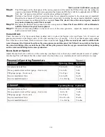
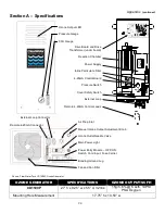


28
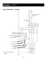
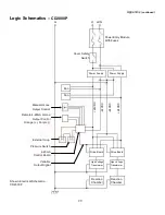
APPENDIX -
Section D
Logic Schematics –
CD1500P
Shown: Electrical Schematic –
CD1500P
G
L1 L2/N
Power Entry Module
With Fuses
High Voltage
Transformer
Drive Board
Remote 4-20mA Ozone
Output Control
Orange (+), Purple (-)
Manual Ozone
Output Control
Fan
Power Supply
Cover Safety
Switch
Power Supply
4-20mA
Control Board
External Loop
Variable
Output Signal
Pressure Switch
Reaction
Chamber
+
2
4
V
D
C
-
2
4
V
D
C
+
2
4
V
D
C
-
2
4
V
D
C


